The Easiest Computational Fluid Dynamics Software
 JP
JP
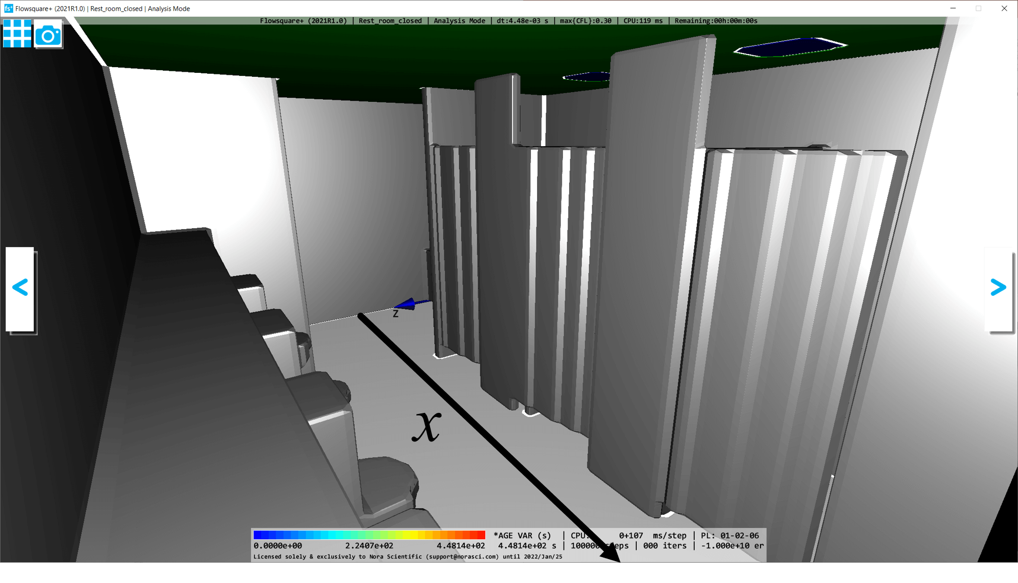
Ventilation in a Public Restroom
1. Introduction
In this tutotial, we perform a simulation of ventilation in a public restroom in a building. All the input files required for the present three cases can be downloaded below. A typical computational time of this case is approximately 10 minutes per 1000 time steps with a typical Core i7 PC with the parallelism setting, parallel = 3, in parameter setting).
Hereafter, descriptions are for "reference case" unless otherwise specified. Also, the "♥" next to the file names means corresponding input file is the same for all the cases.
Reference case
(closed window & door)
2. Domain specification
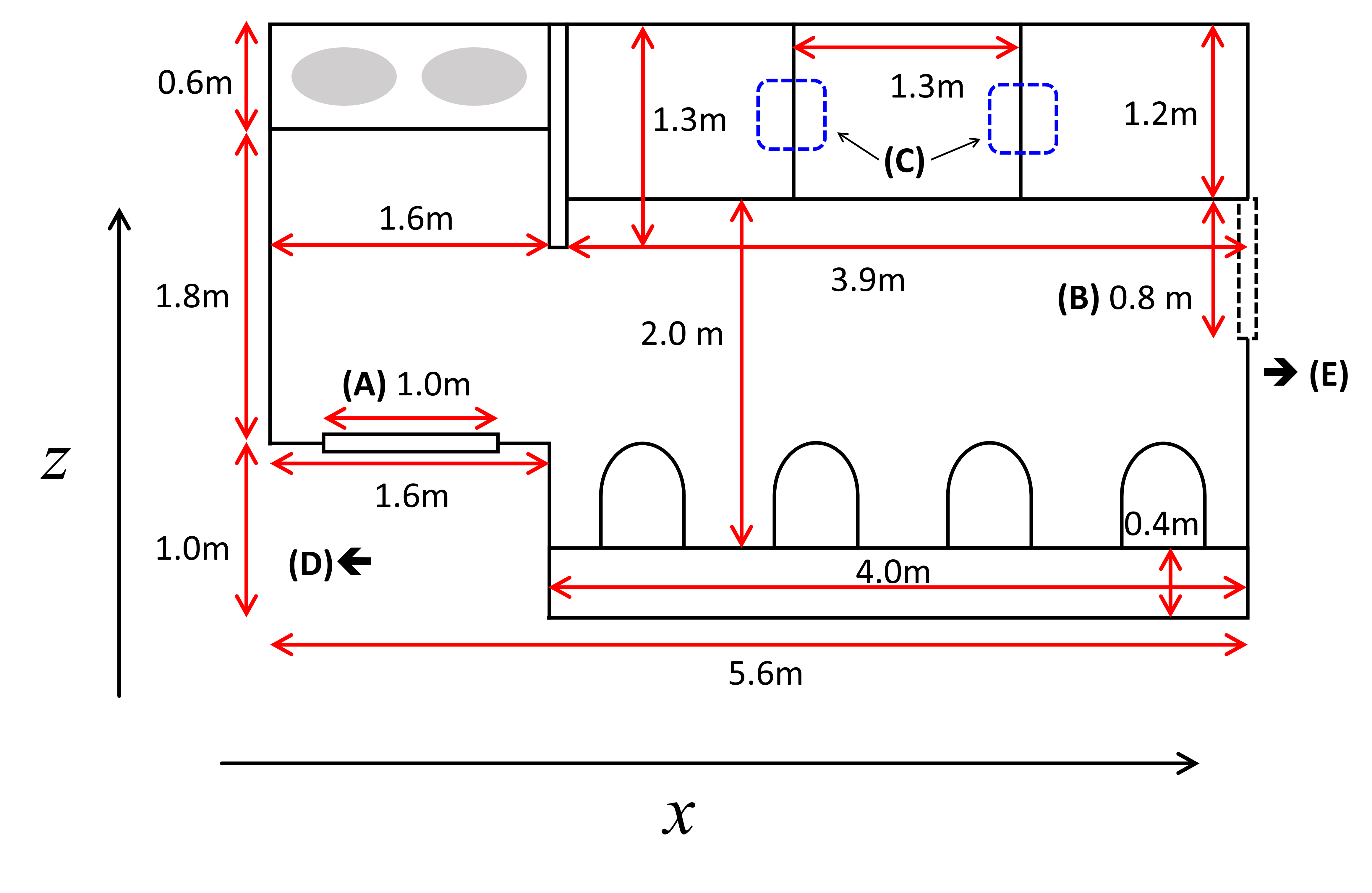
The below figure shows a bird's-eye view of present simulation domain dimensions which are based on measurement. The items (A) - (E) are expain below, and they are related to the physical boundary conditions of the three cases, "reference case", "window opened" and "door opened" cases.
- (A) Door (small gap at the bottom of the door for ventilation)
- (B) Window
- (C) Ventilation fans attached on the ceiling
- (D) To the corridor in the building
- (E) To outside of the building
The air in the restroom is pumped out of the restroom by the ventilation fans equipped on the ceiling (threfore negative pressure in the room). The fresh air from the outside or the corridor naturally flows in the room through the gap at the bottom of the door, opened window and/or opened door, depending on the cases.
Also, in the present simulations, we consider region outside of the building (region E in below figure) for about x=1.4 (m). This is to avoid the situation where the air flowing in through the opened window is directly from the coputational boundary (unknown information). If you can spend more computational resources, you may want to enlarge the size of the outside region.
3. Construction of Simulation Domain
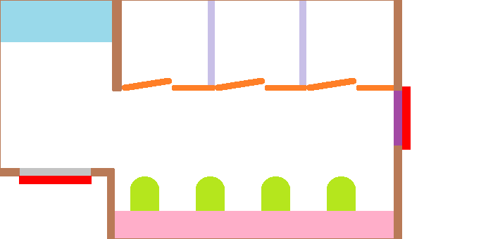
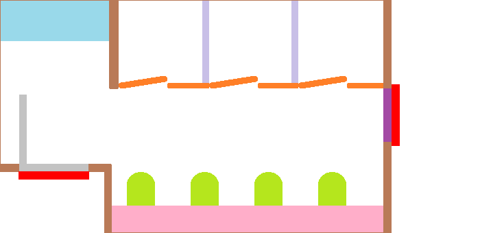
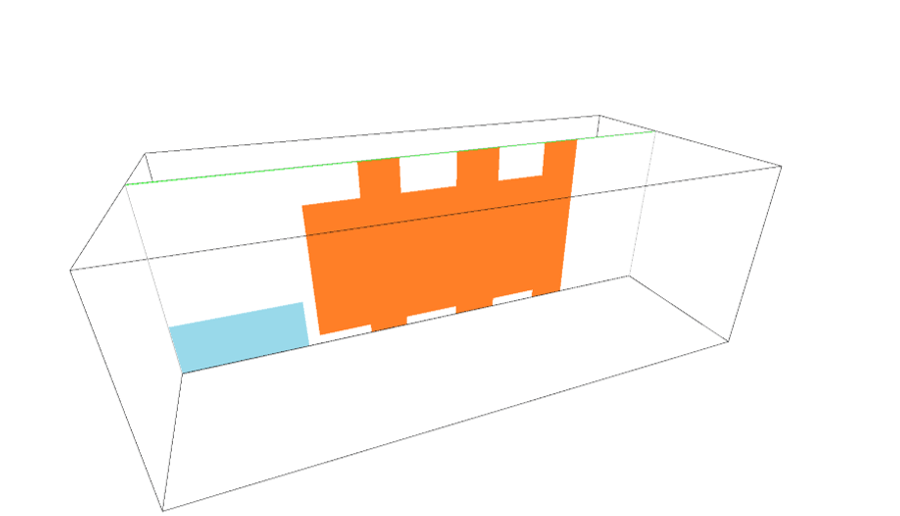
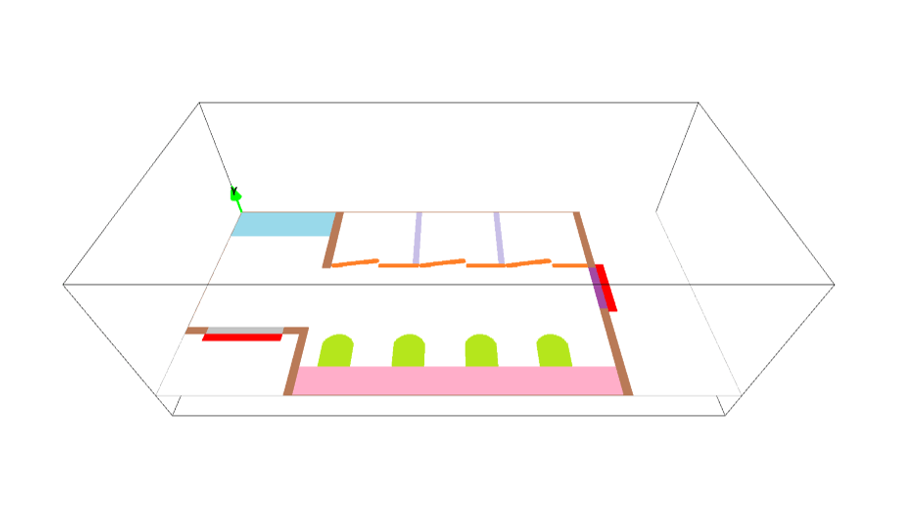
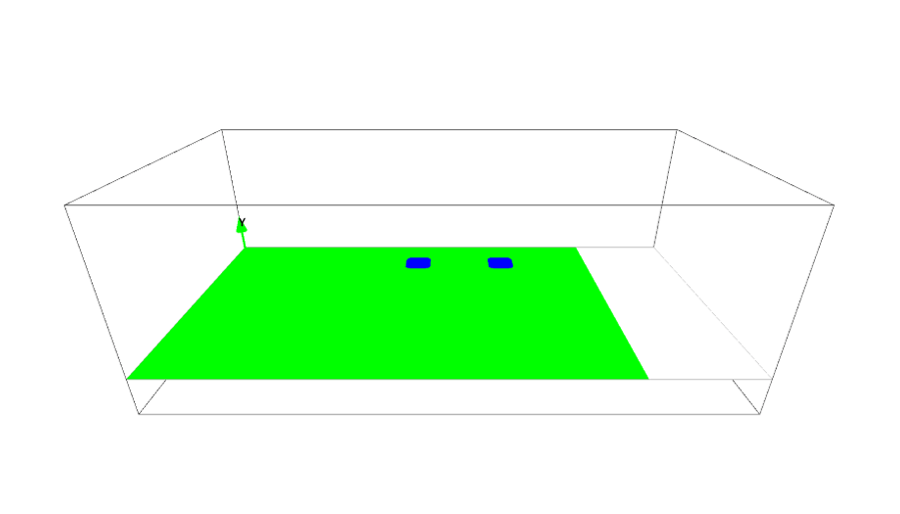
General rule of constructing 3D boundary conditions is explained in here. In the present simulations, following colors are used for different parts of the domain.
- Wall, window and door (non-preset colors)
- Floor (preset black)
- Ceiling (preset green)
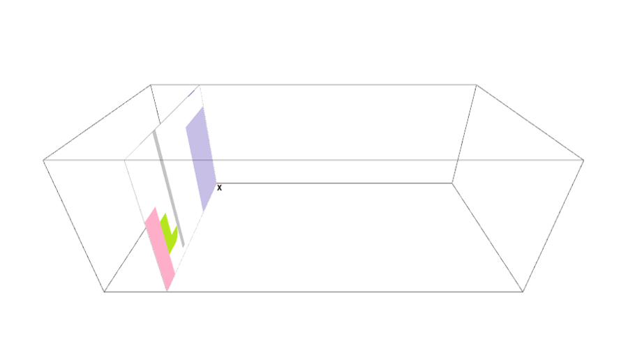
- Ventilation fans (preset blue)
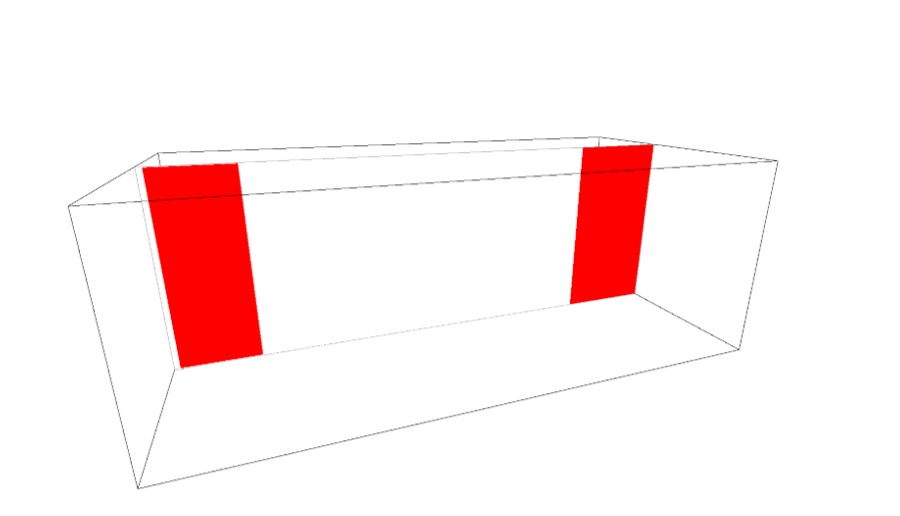
- Initialization of the age variable (preset red)
Each of these parts specified by one of above colors is constructed using "(b) Model constructed by third angle projection".
The paint image pixel sizes can be irrelevant to actual physical domain dimensions. However, it is a good habit to use more or less similar aspect ratio between images and domain dimensions. In the present cases, 1 (m) length corresponds to 100 pixels in the paint images.
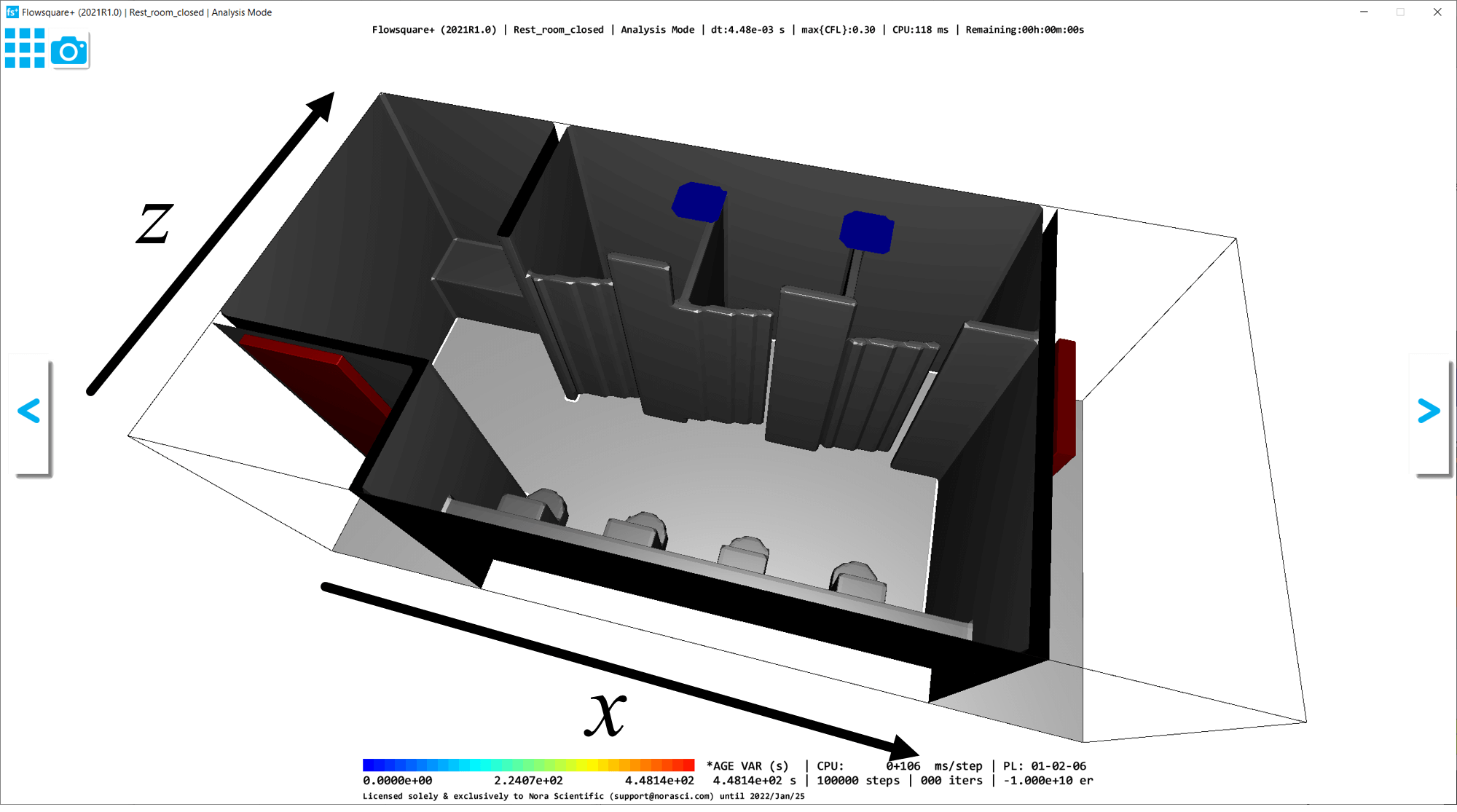
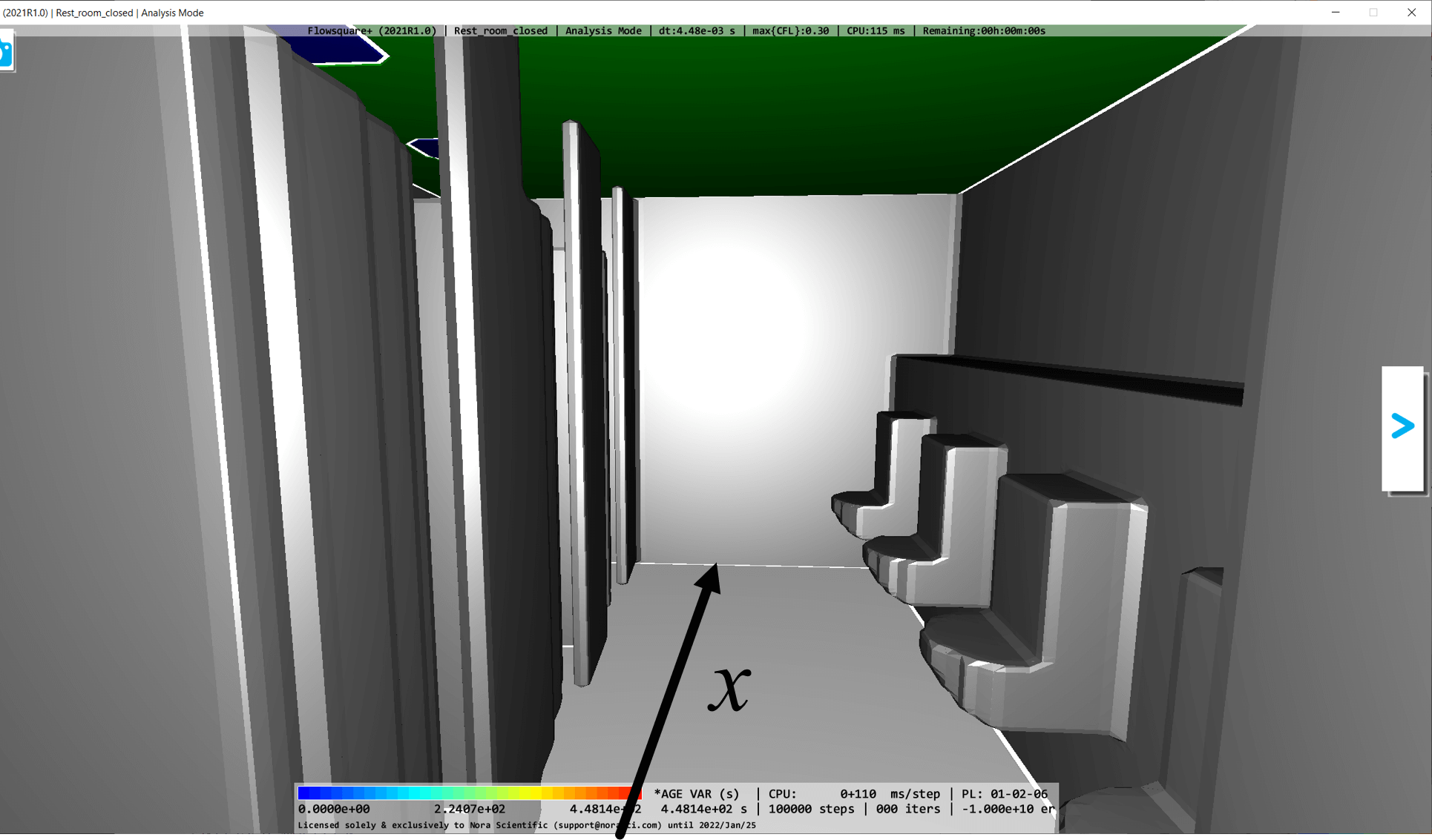
Below images are for "reference case".


4. Simulation Parameters
Several important parameters are explained here. More thorough information about parameters can be found here.
- cmode = 0
Taken as 0 for the fluid simulation mode (constant temperature and density). - ageFlag = 1
To use the age varialbe during simulation, choose 1. - lx = 7.0
The domain length in X-direction is 7.0 m. This includes the region outside the building. - ly = 2.5
The domain length in Y-direction is 2.5 m. - lz = 3.4
The domain length in Z-direction is 3.4 m. - nx = 210、ny = 150、nz 102
The number of mesh points needs be determined based on the required spatial resolution. Here, we will use (nx, ny, nz) = (210, 150, 102). The thinnest part of the 3D model (in this case, perhaps wall) should be resolved by few mesh points at least, unless the part is on the computational boundary. - presW, rhoW
Pressure is 100,000 (Pa), and fluid density is 1.2 (kg/m^3). - vinB
The fluid velocity from the ventilation fans (preset blue) is taken as 1 m/s in y-direction. - uinR、vinR、winR
We want the age variable to start accumulating the residence time after entering the room. Thus, we need to set \(a=0\) in the outside region. To do that, red color is added right outside of the door and window with the relevant velocity parameters, uinR = vinR = winR = " - " (hyphen). This does not influence the velocity, but constrain the age variable to be zero. See #3 in the Section 2. - openPresFlag = 1
The present simulation domain has quasi-closed configuration. Therefore, the pressure condition at the open boundaries on the computational boundaries is treated by Dirichlet condition (openPresFlag = 1).
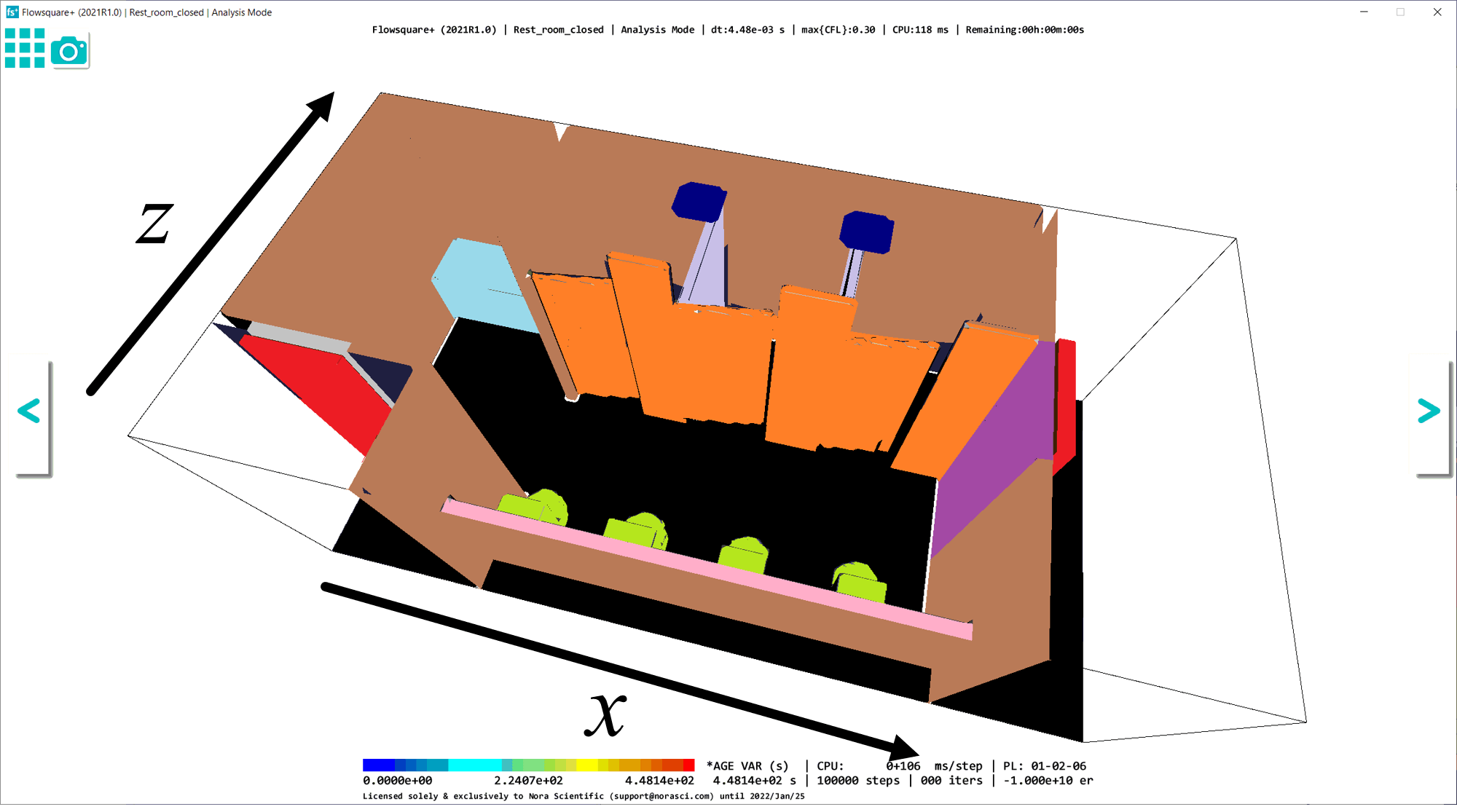
5. Simulation results
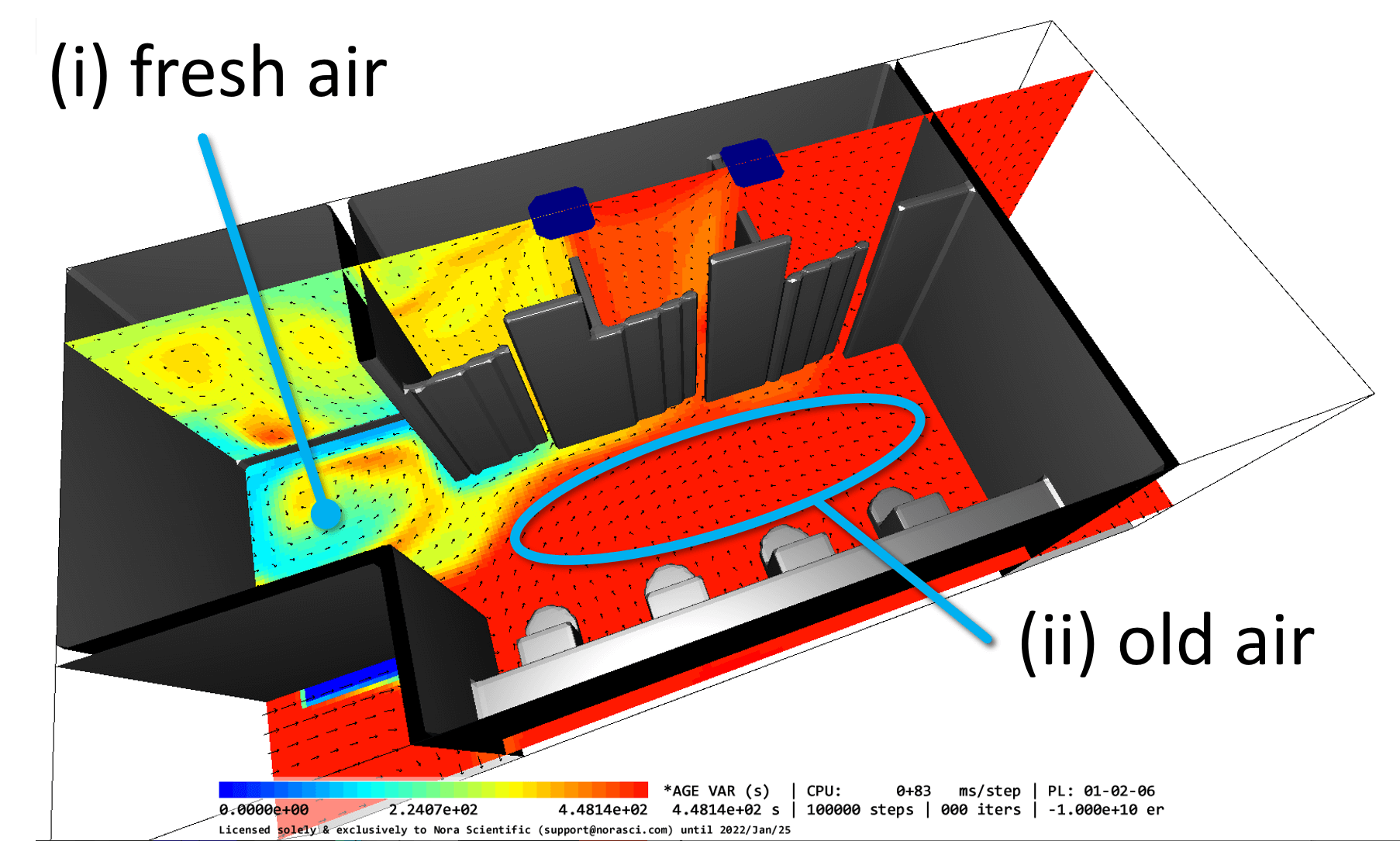
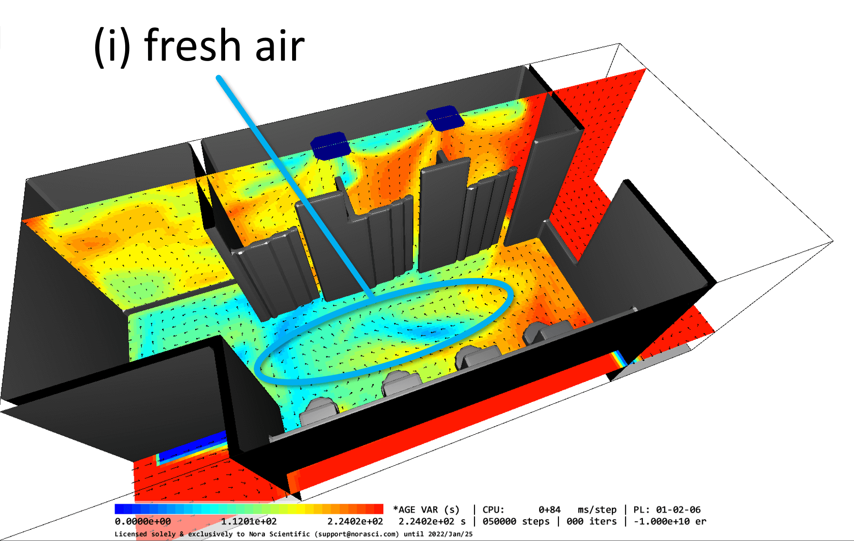
Below figures show the age variable field on the XY and XZ cross-sections. Velocity vectors are also superimposed on the planes.
Age variable corresponds to the local residence time of the flow. Therefore, in regions with a small age variable (blue, green colors on the color map), the air is quickly replaced by the air coming from the outside the room. Such regions are denoted by "(i) fresh air" in the figures. On the other hand, in regions with a large age variable (red color on the color map), the air stays where they are for long time and the ventilation is not so effective in such regions. Such regions are denoted by "(ii) old air" in the figures below. (*Note that in the present simulations, the outside air flowing in the room yields \(a=0\) at the red boundary)
Among the three cases considered with the same ventilation fans, the "reference case" shows poorest ventilation overall, whereas "window opened" case shows most uniform ventilation throughout the restroom.