The Easiest Computational Fluid Dynamics Software
 JP
JP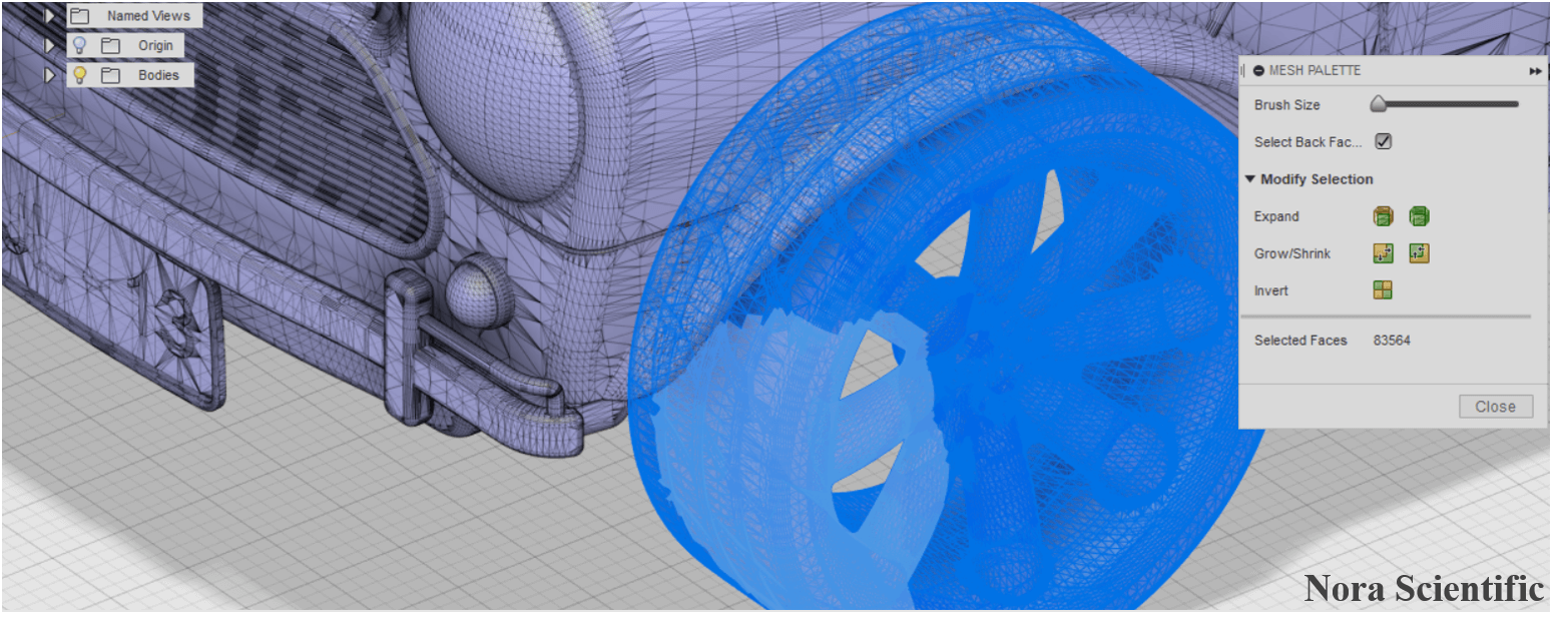
3D CAD (STL) Model and its Optimization
- Optimization steps
- 1. Optimal CAD model for Flowsquare+?
- 2. Installing Fusion 360 and User Rregistration
- 3. Preference Setting
- 4. Opening a STL file
- 5. Deleting Underresolved Parts
- 6. Deleting Moving Parts (If Discontinuity Exists)
- 7. Deleting Zero-Thickness, Open Surfaces
- 8. Deleting Remaining Unphysical Parts
- 9. Generating Closed Mesh
- 10. Reducing and Uniformizing Mesh
- (10a. Details of Uniformizing Mesh)
- 11. Saving the Optimized Model
- 12. Simulation Example with the Optimized Model
1. Optimal CAD model for Flowsquare+?
3D CAD desined model (STL file) can be used in Flowsquare+ to specify boundary configuration for a simulation. To use a STL model in Flowsquare+, the model needs to be named as bc.stl, and stored in the same directory as all other input files. If the file exists in the right directory, the STL file is automatically loaded at the Boundary confirmation window after execution of Flowsquare+. If the model is not appropriately loaded, please refer to the FAQ page.
You can designed your own CAD model from scrach, or just download one as there are many CAD files are available on the internet, to perform a flow simulation around the model.
However, some CAD models have some aspects that are not suitable for fluid simulation. Therefore, the user need to examine the CAD file carefully, and if needed, perform some optimization on their own, before using the model for Flowsquare+ simulations.
Typically, following items need to be examined.
- Parts that are smaller than specified spatial resolution→to be deleted.
- Parts that moves (rotates) such as car wheels, if they cause unphysical discontinuity with other boundaries→to be deleted.
- Unphysical zero-thickness, open surfaces→to be deleted.
- Polygon with a very large or small mesh aspect ratio→to be deleted or re-meshed
Here, we use a free, downaloadable STL file of a car (~30MB) from CAD file sharing services suhc as GRABCAD, to explain how to perform above optimization for a STL model by using Fusion 360 CAD tool. You can also use any CAD tool, since most of them are capable of what explained below.
2. Installing Fusion 360 and User Rregistration
Users with non-commertial purposes can use AUTODESK's Fusion 360 for free*. To use this benefit, down load a free trial Fusion 360, by creating a user account.
This page uses Fusion 360, but any 3D CAD tool can handle optimization introduced here.
*Please check terms and conditions. They may change in future.
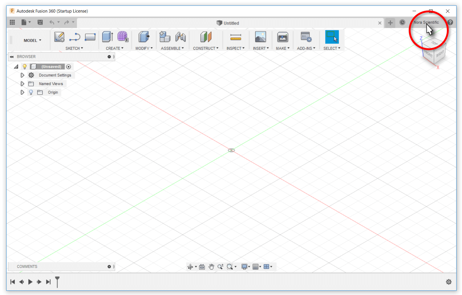
3. Preference Setting
- First, some setting needs to be done. After executing Fusion 360, click on the user name tab on the right-top (in the figure the area of "Nora Scientific" name).
- Then, click on the "Preference" from the displayed manu.
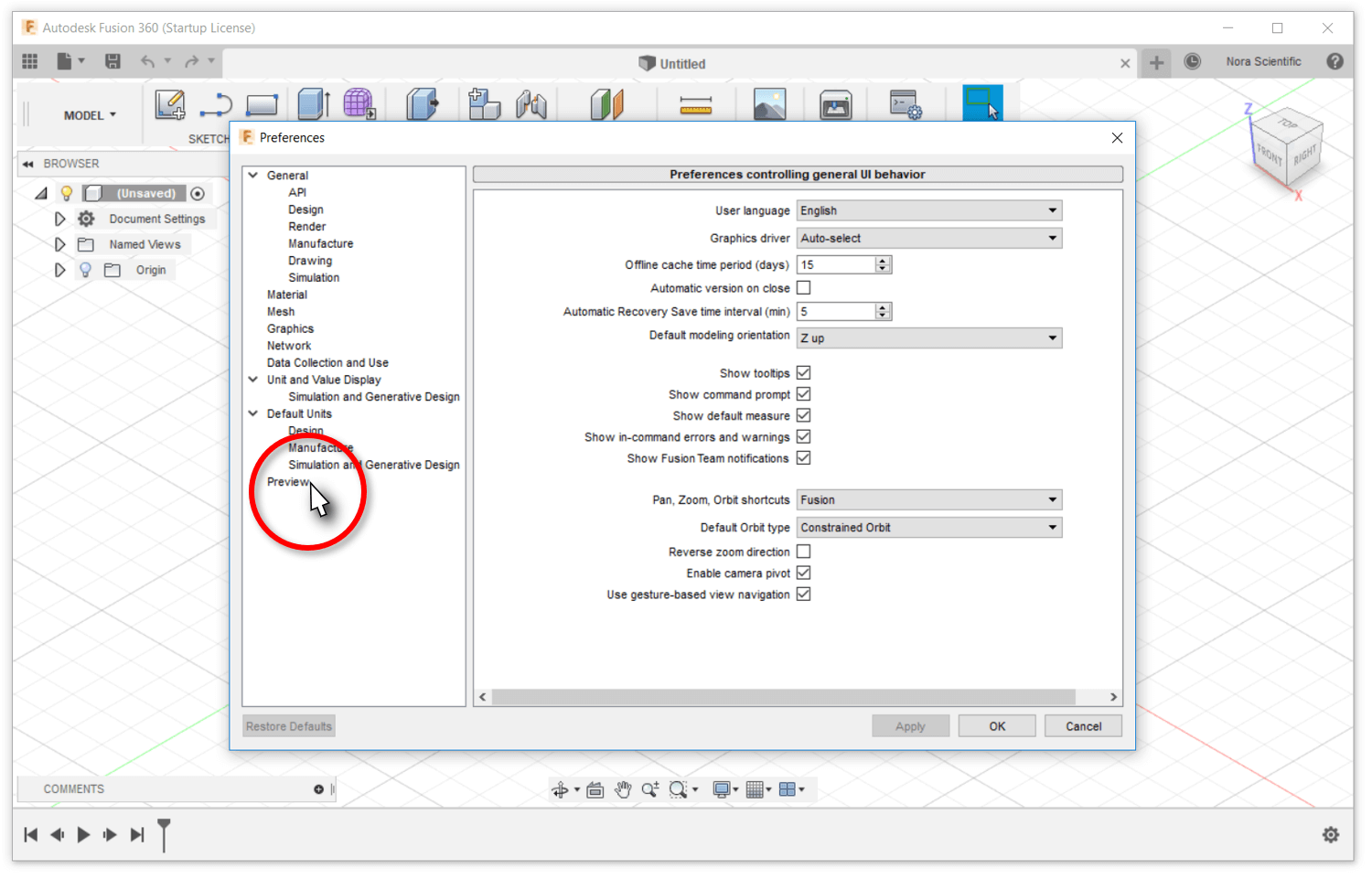
- Select "Preview" from the left manu of the Preference Window.
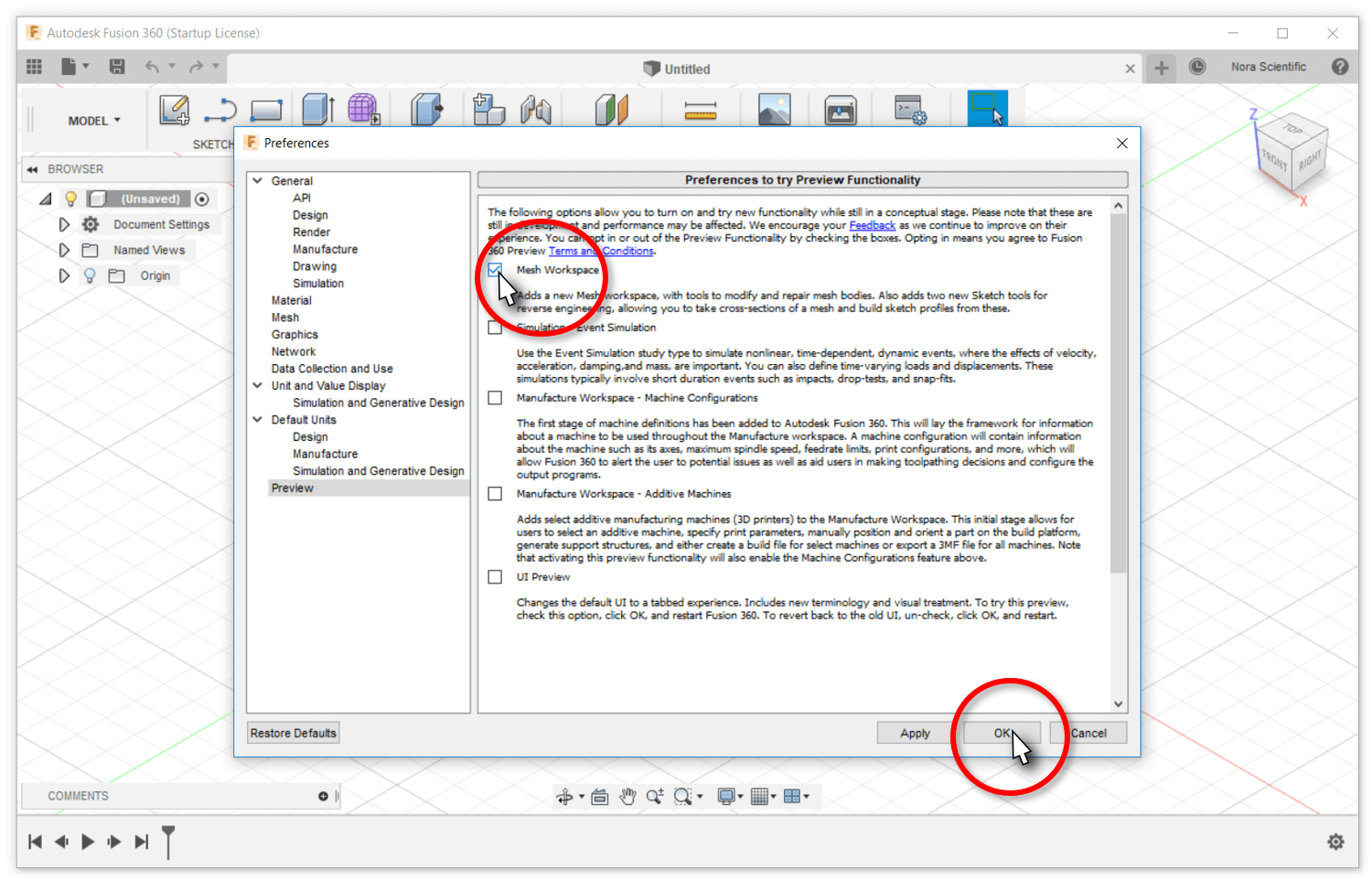
- Check the box of "Mesh Workspace", then press the OK button.
- Now we are good to go.
4. Opening a STL file
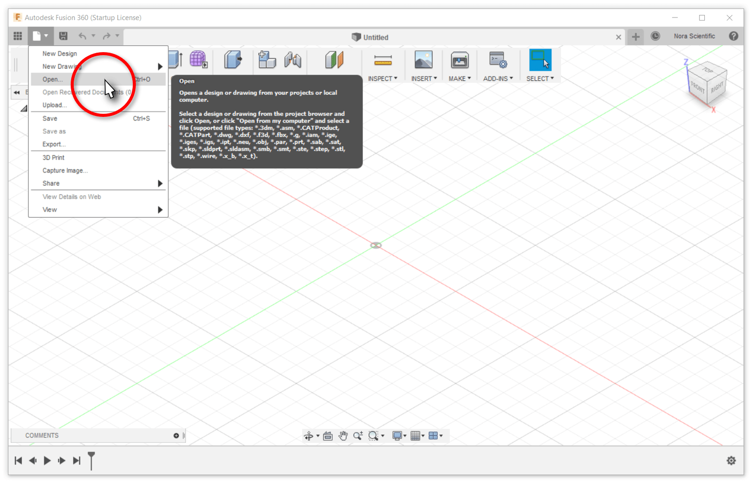
- After opening Fusion 360, click on the file icon
 on the left-top, then click on "Open..." from the displayed menu.
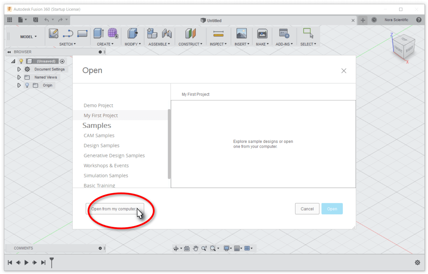
- Click on the "Open from my computer" button on the displayed small window, choose and open a STL file.
- The example STL file of a car we will be using was loaded and displayed in the field.
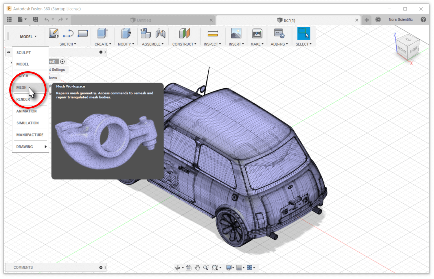
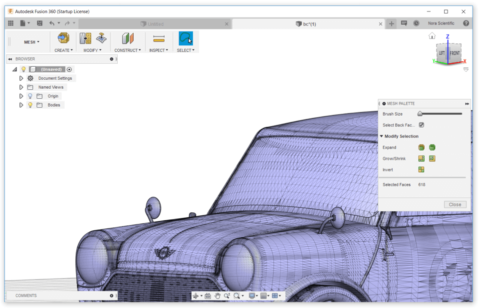
- Click on the "MODEL" button on the left-top, and then click on the "MESH" button from the displayed menu to open Mesh Workspace.
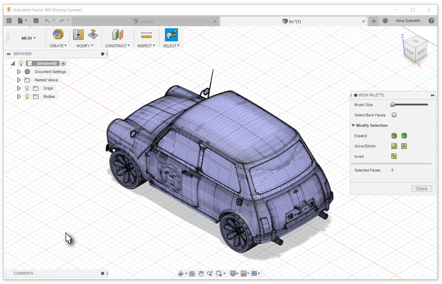
- The mesh workspace now is ready for some optimization!
5. Deleting Underresolved Parts
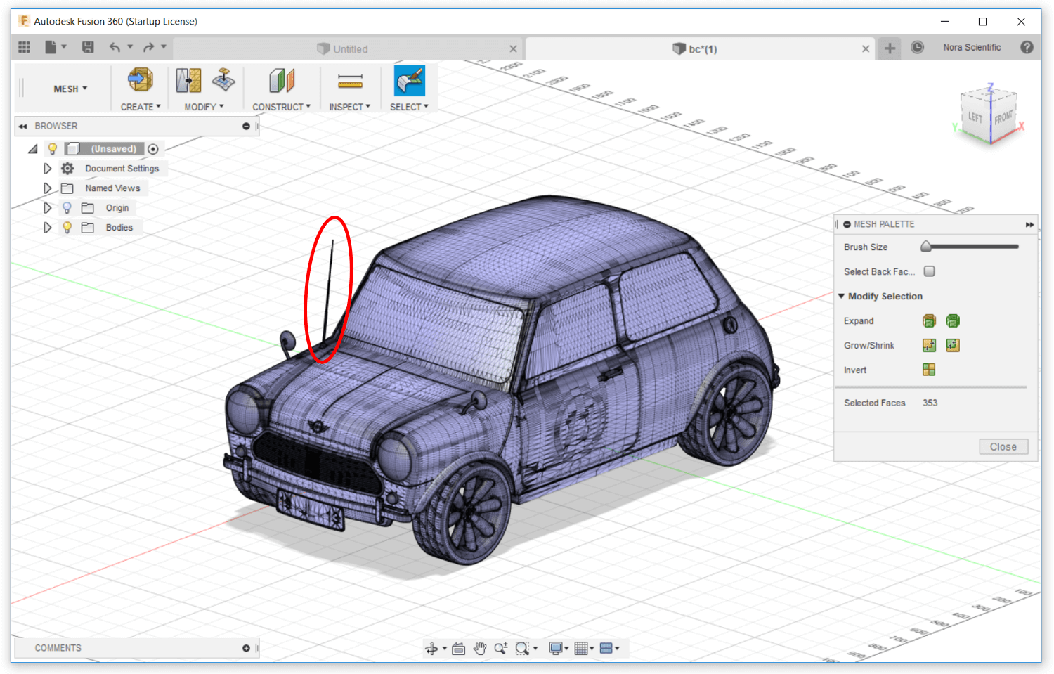
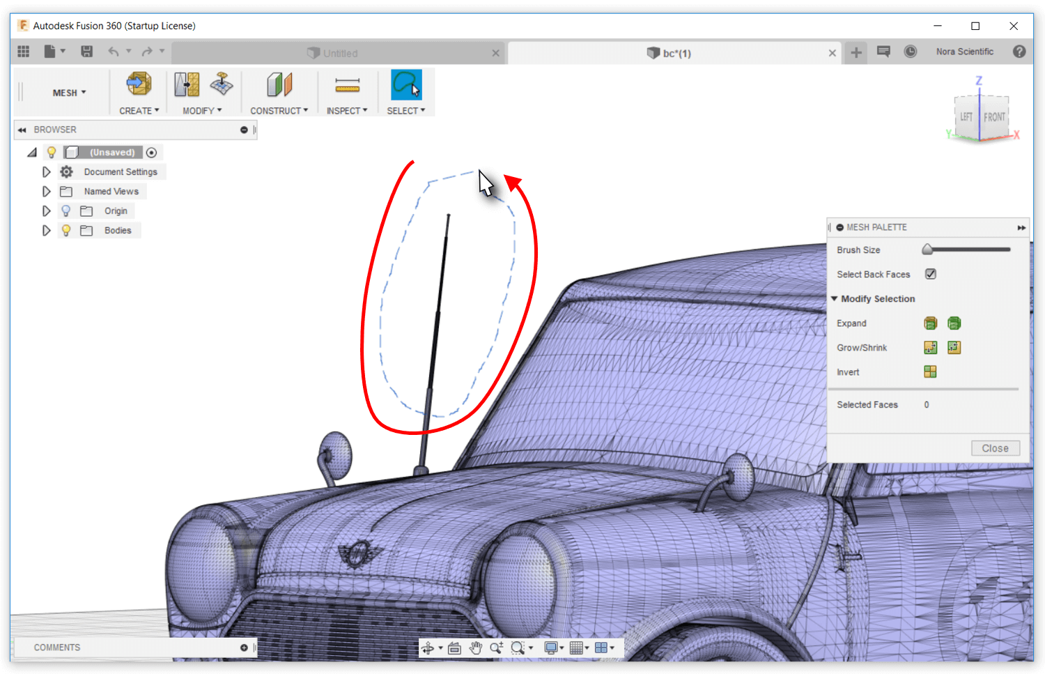
- To make your life easy, let's rotate the view a little. By default, you can rotate view with SHIFT and DRAG with a mouse middle button. The antenna (highlited in the figure) is too thin to resolve in the simulation, so is removed here.
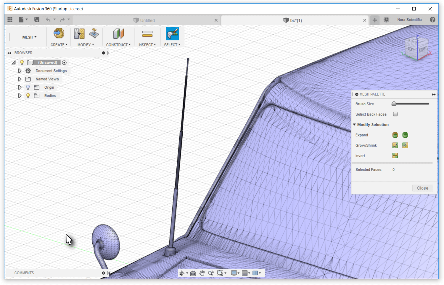
- Zoom into the part (antenna) that needs to be removed. By default, Fusion 360 can zoom with a mouse wheel.
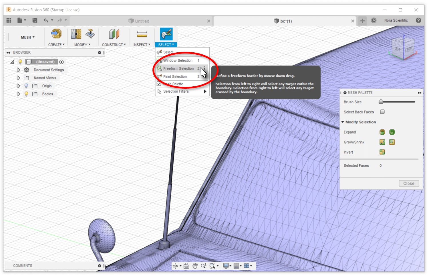
- Click on "SELECT" on the right side of the mesh workspace menu, and then click on "Freeform Selection" from the displayed menu. With this freeform selection, you can select the part of interest by drawing a freeform border with mouse drag operation.
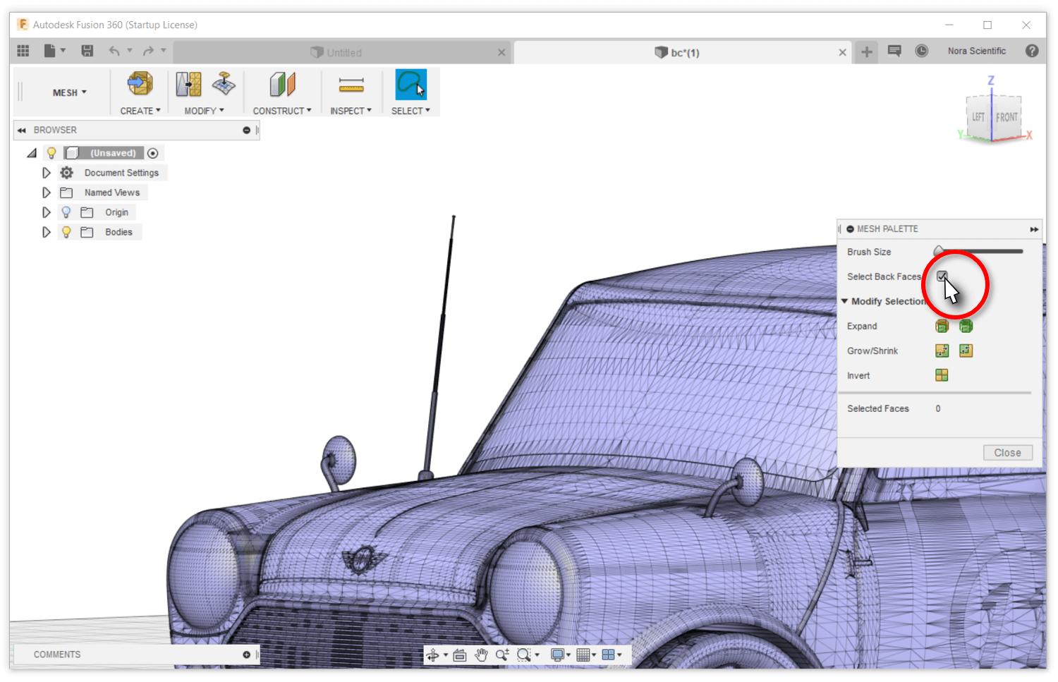
- Then, check the box of "Select Back Faces" on the MESH PALETTE. With this option, you can select both front and behind meshes in the freeform border.
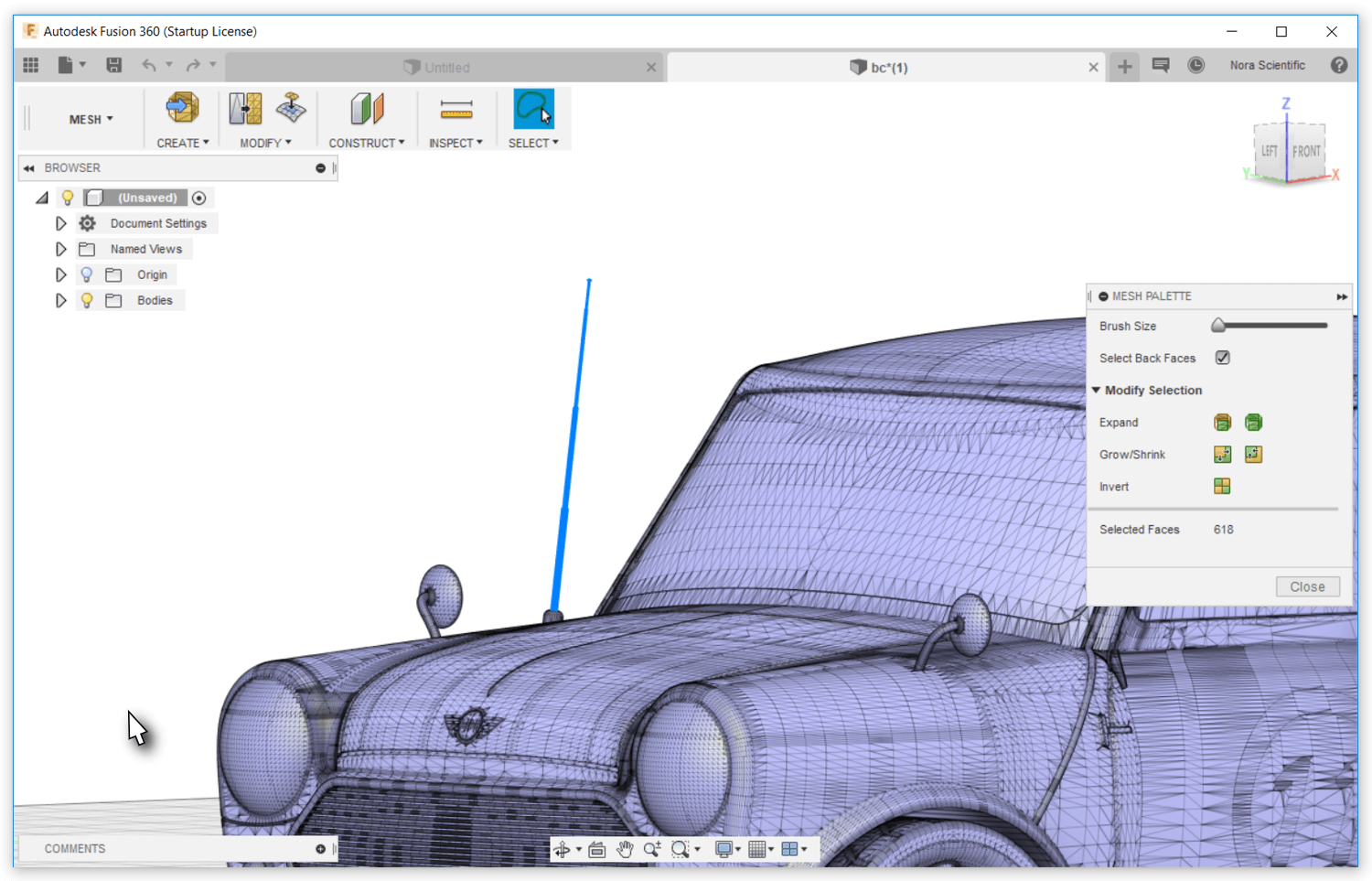
- Draw a border around the part of interest (antenna). You can select a part of the part repeatedly until selecting the entire part of interest. Please be careful not to include any part you do not want to delete.
- The part of interest (antenna) is now selected.
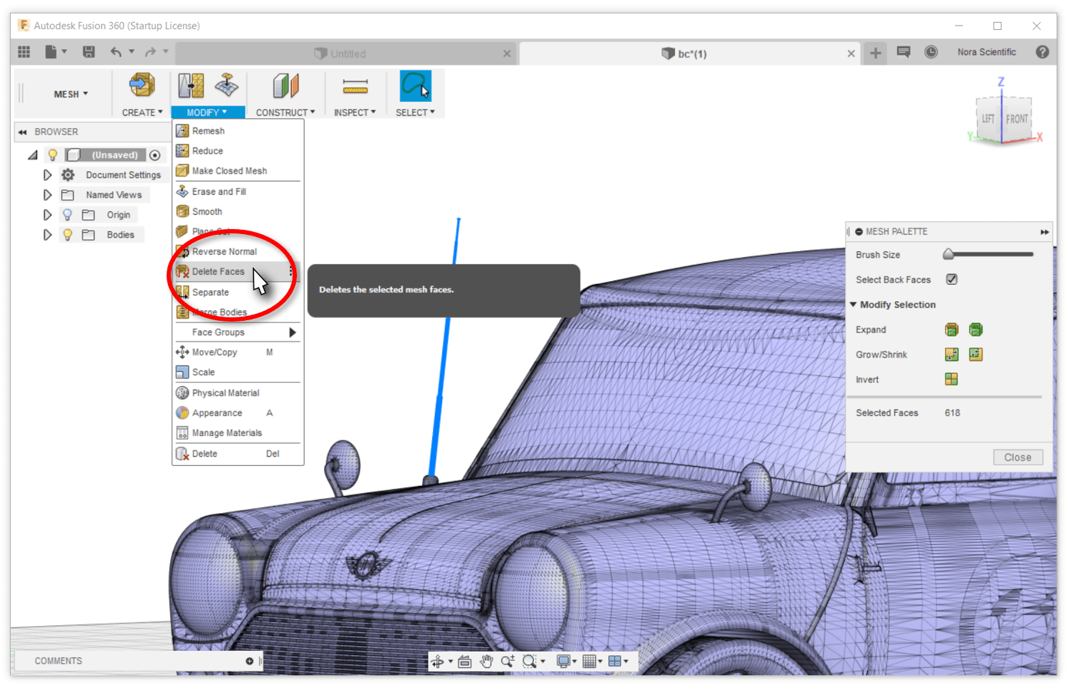
- Click on "MODIFY" on the mesh workspace menu, and then click on the "Delete Faces" on the displayed menu.
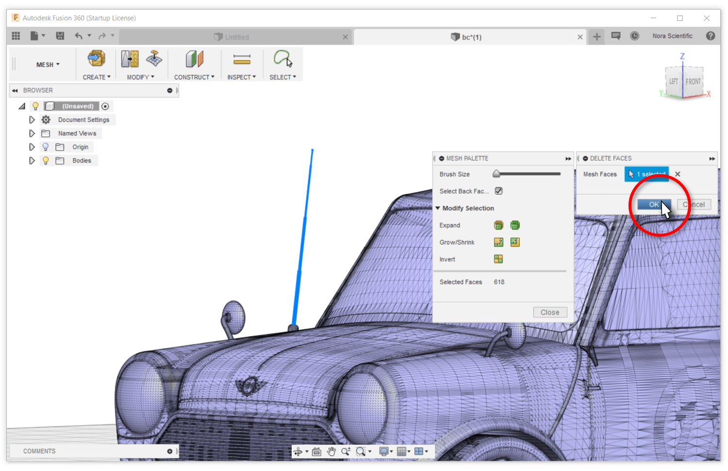
- Click on the "OK" button in the "DELETE FACES" small window. The selected part will be deleted.
- The antenna was successfully deleted!
6. Deleting Moving Parts (If Discontinuity Exists)
The air flows around a moving car at the traveling speed respect to the car, and so does the ground (road surface) relative to the car. The four wheels on the car rotate to match the the traveling speed as well. However, the Flowsquare+ can not handle such moving parts. Therefore, for a simulation of a flow around a moving car, we need to consider stationary wheels, which cause discontiuity between the wheels and the ground.
To avoid such circumstances, these moving parts may be deleted from the model before the simulation.
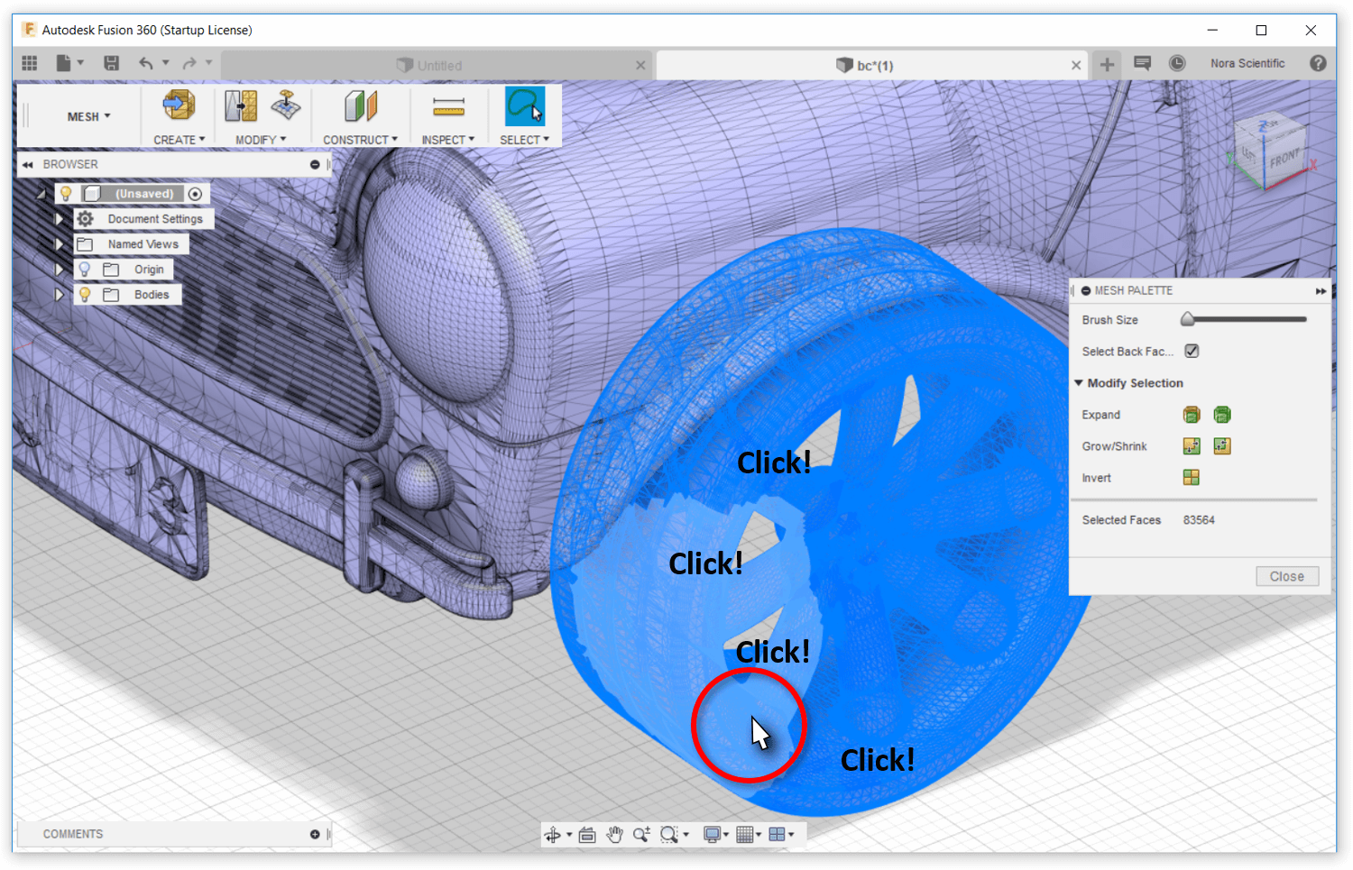
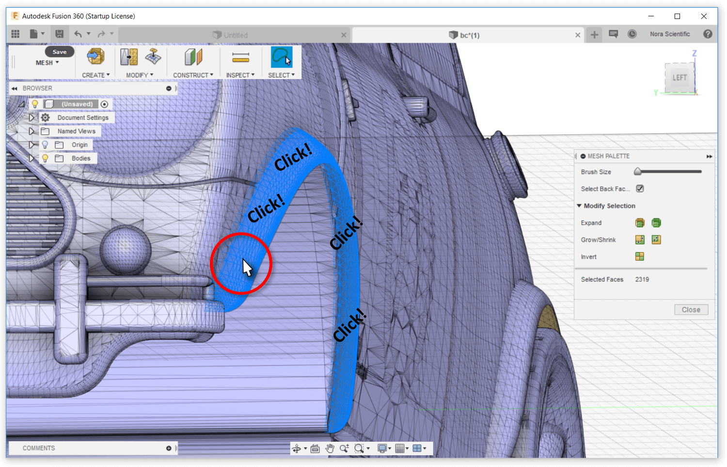
- Zoom into a moving part (wheel). Select entire surface of the part with mouse click(s) and/or by drawing border with the "Freeform Selection" tool.
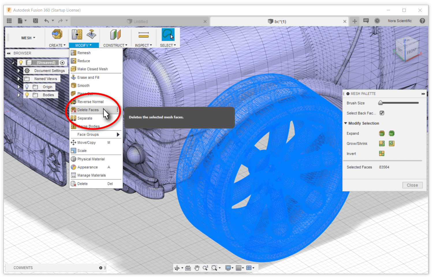
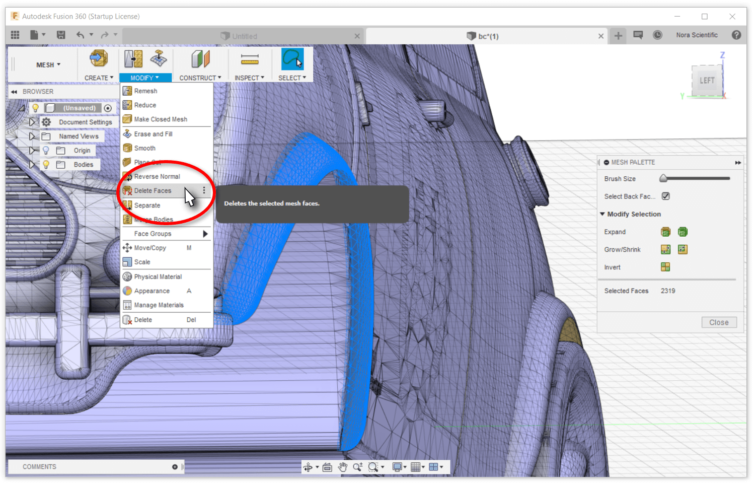
- Click on "MODIFY" on the mesh workspace menu, and then click on the "Delete Faces" on the displayed menu. Then, click on the "OK" button in the "DELETE FACES" small window. The selected part will be deleted.
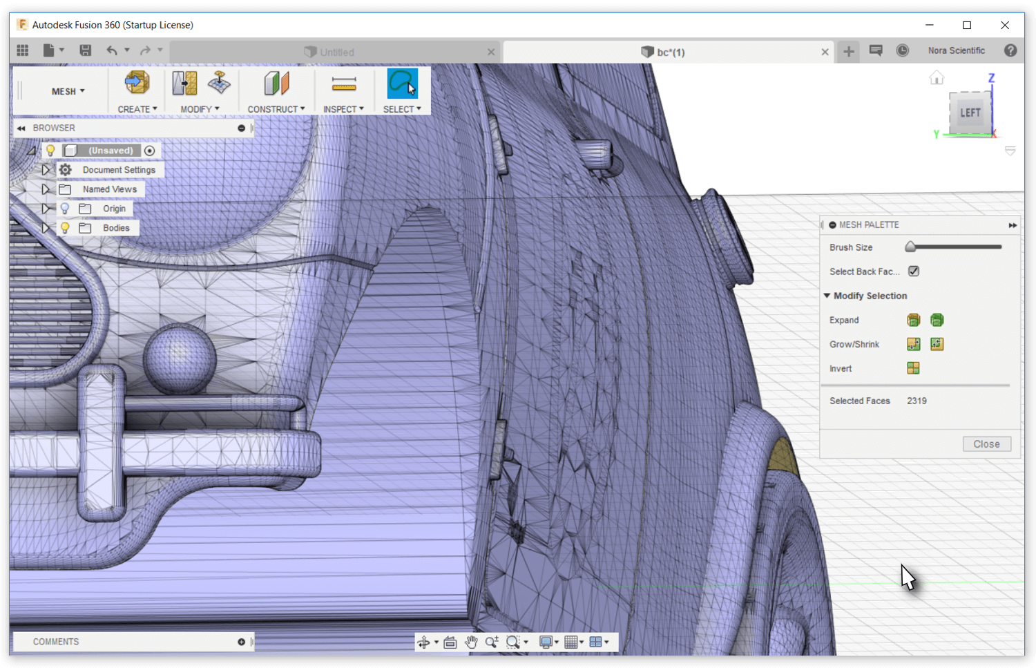
- If the entire part wasn't selected/deleted, you can repeat the above procedure until entire of the part is deleted.
7. Deleting Zero-Thickness, Open Surfaces
Physically, any part needs to have a finite thickness. Some publically avaialble STL model may have unphysical zero-thickness parts, which are not too visually important. These unphysical parts need to be deleted before using for the simulation.
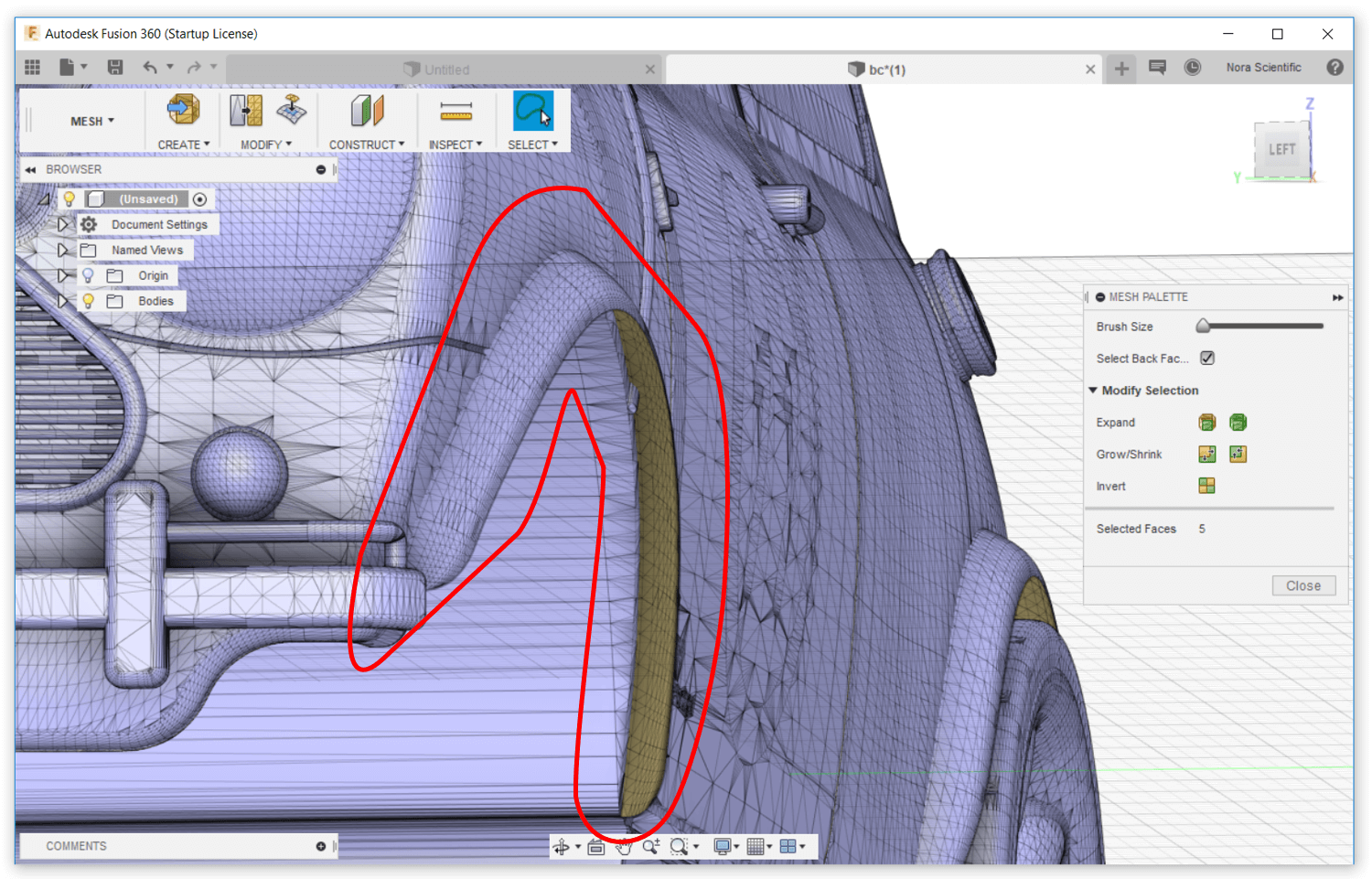
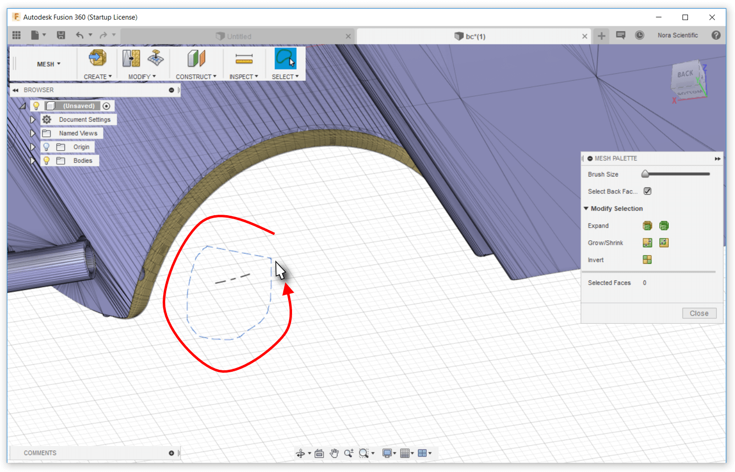
- In Fusion 360, the back side of an open surface is visualized with a dark yellow-ish color. Such a part (fender as an example in the figure) with an open surface needs to be deleted.
- Zoom into the open surface (fender). Select the entire part (fender) to be deleted with mouse clicks and/or by drawing border with the "Freeform Selection" tool.
- Click on "MODIFY" on the mesh workspace menu, and then click on the "Delete Faces" on the displayed menu. Then, click on the "OK" button in the "DELETE FACES" small window. The selected part will be deleted.
- The open surface was deleted.
8. Deleting Remaining Unphysical Parts
Some parts may be remaining after the above procedure of deleting inappropriate parts. Such unphysical leftover parts also need to be deleted.
- Find such unphysical parts by carefully examining the STL model.
- As always, zoom into the open surface (fender). Select the entire part (fender) to be deleted with mouse clicks and/or by drawing border with the "Freeform Selection" tool.
- As always, click on "MODIFY" on the mesh workspace menu, and then click on the "Delete Faces" on the displayed menu. Then, click on the "OK" button in the "DELETE FACES" small window. The selected part will be deleted.
- Repeat above procedures untill wall unwanted parts are removed from the STL mode.
9. Generating Closed Mesh
After above procedure of deleting parts, the model has some open surface around the deleted parts' original positions. These open surfaces need to be closed.
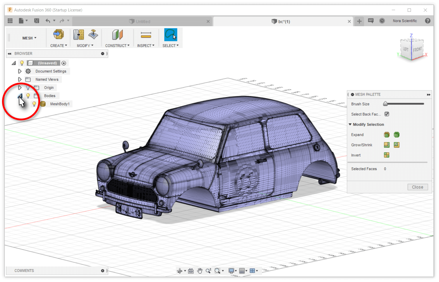
- Click on the triangle icon
 displayed on the browser list on the left side of Fusion 360, and open the body item.
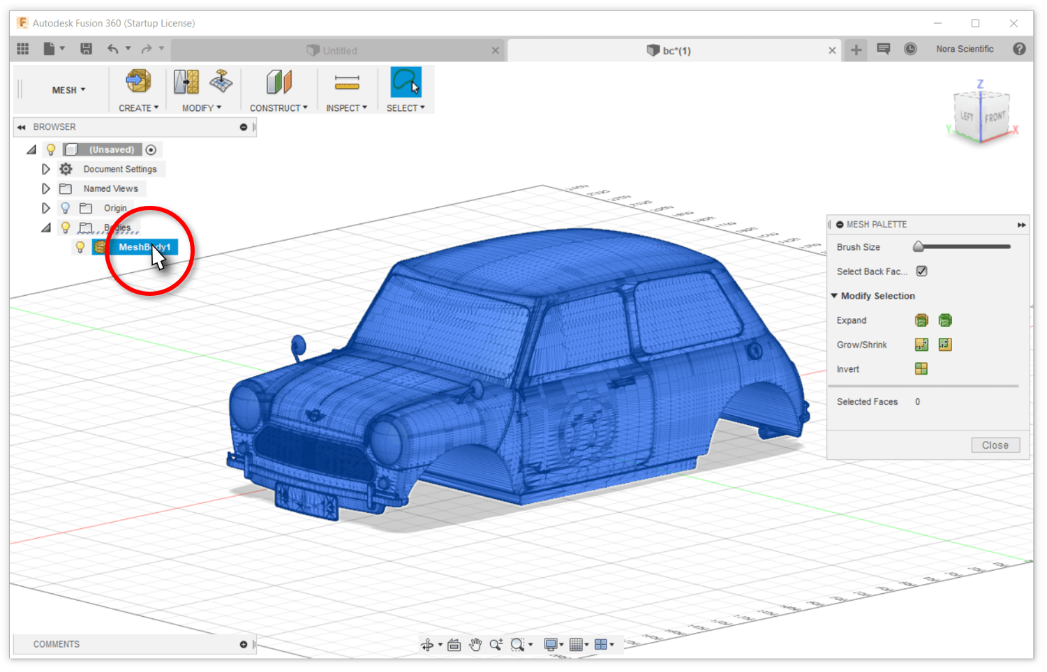
- Select the "MeshBody1" from the displayed body item(s)l. This "MeshBody1" is the STL model from which all unwanted parts were deleted in above.
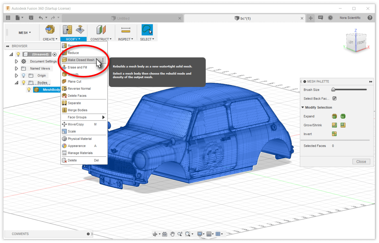
- Click on "MODIFY" on the workspace menu, and then click on "Make Closed Mesh".
- Adjust the mesh density (to 256 for example) on the "MAKE CLOSED MESH" window. A larger density generates a closer model but the file size becomes larger too. Click on the "OK" button to generate a new model with fully closed mesh.
10. Reducing and Uniformizing Mesh
To reduce the STL file size and accelerate the visualization speed during the simulation, mesh reduction may be performed.
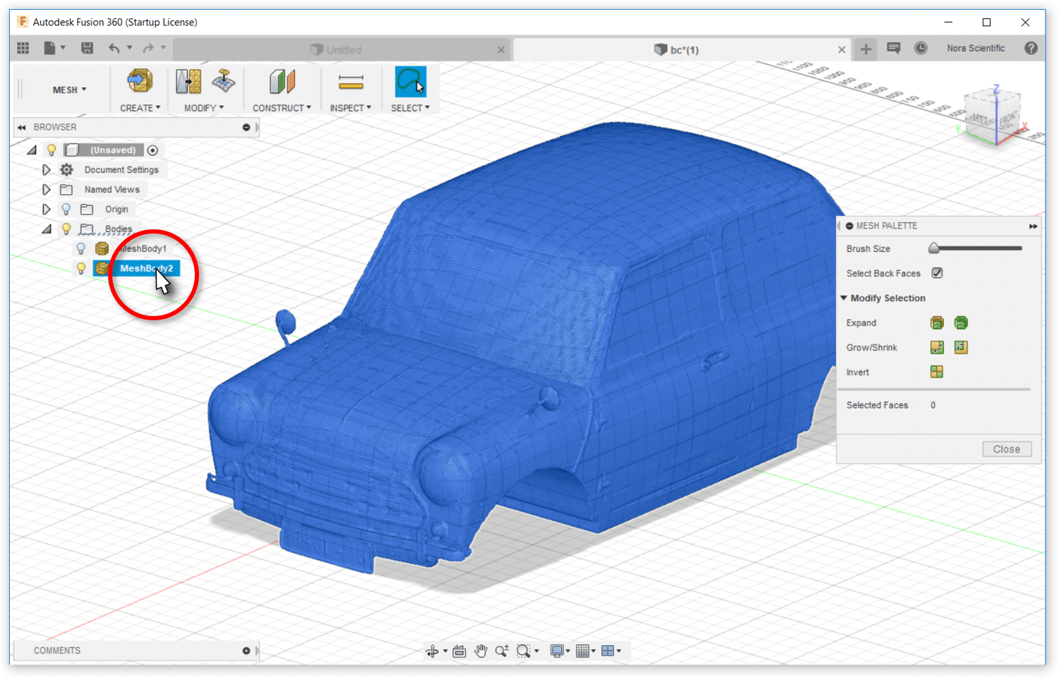
- Select "MeshBody2", which are the closed mesh model generated in the above procedures.
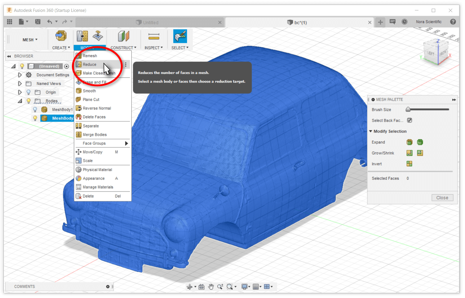
- Click on "MODIFY" on the workspace menu, and then click on "Reduce".
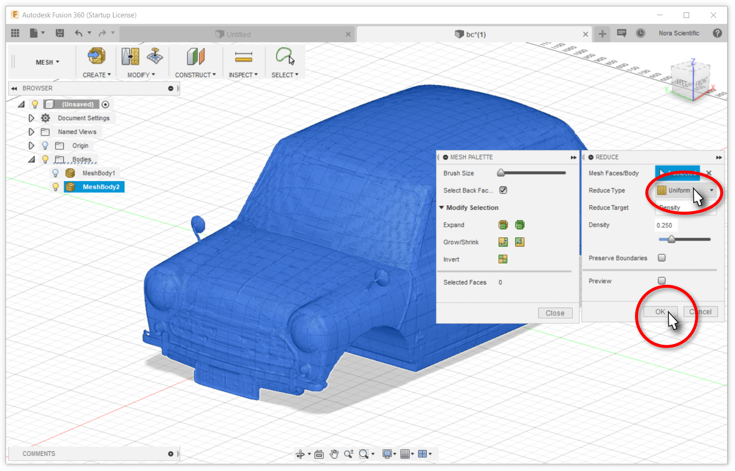
- Select "Uniform" as "Reduce Type" to generate mesh with aspect ratio close to unity, which is good for simulation with Flowsquare+ in general. "Density" may be modified here, too. Click on the "OK" button to reduce the number of mesh.
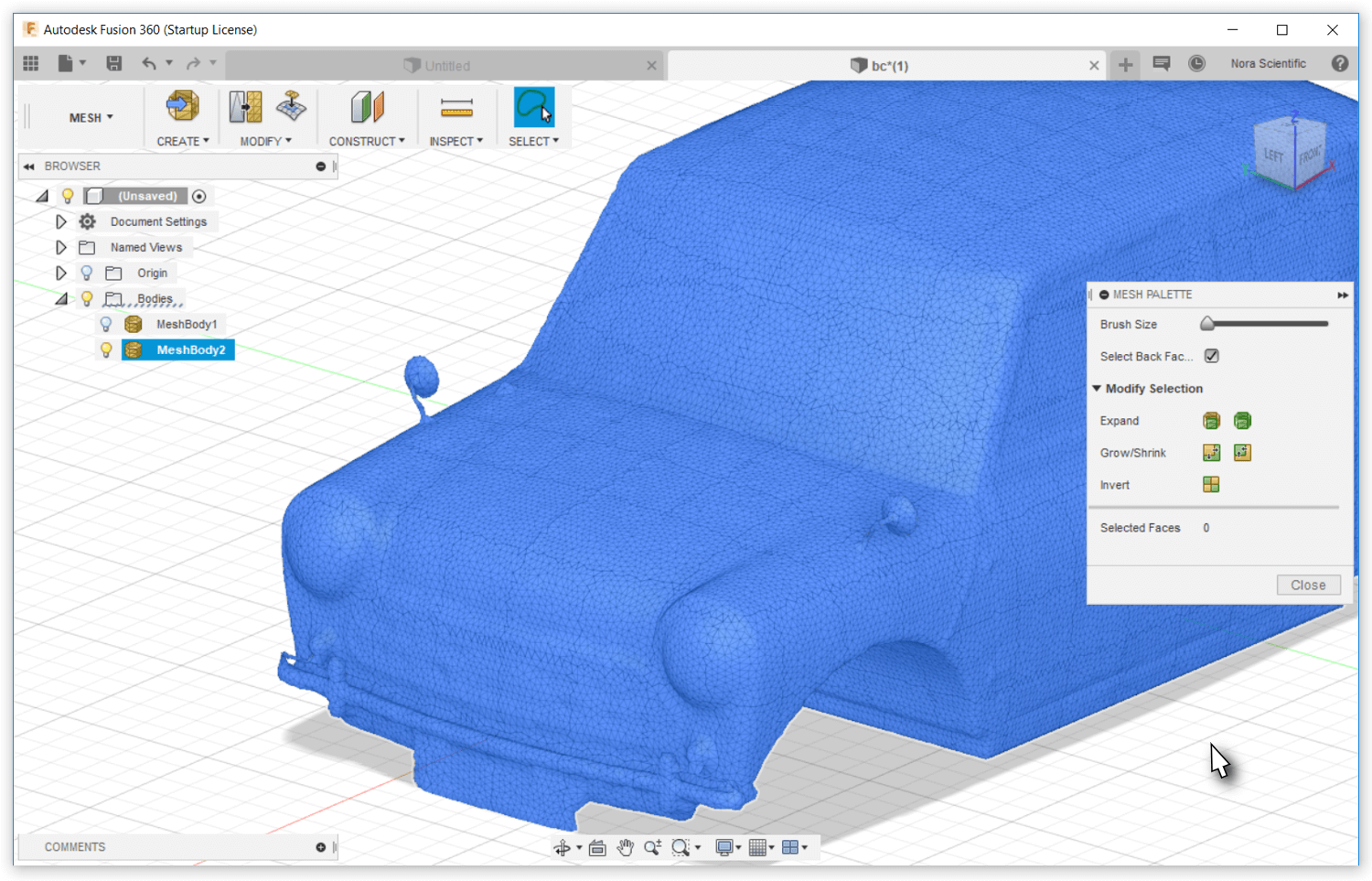
- The mesh is now reduced and more uniform!
10a. Details of Uniformizing Mesh
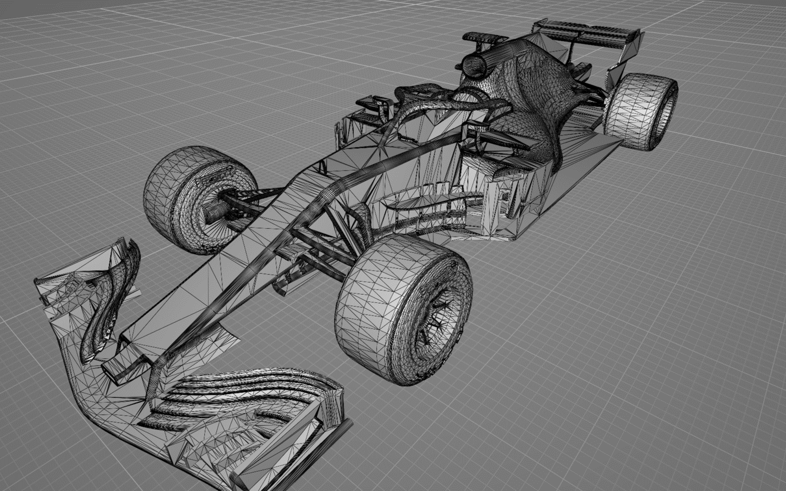
In general, many of publicaly available STL models consist of polygon meshes based on the local curvature, and the mesh size and shape change with the local model shapes.
On the other hand, uniform meshes are desired in Flowsquare+ to construct boundary conditions from the STL file.
Below figures show a comparison of an unoptimized (publicaly available) STL model and an optimized STL model with mesh uniformity following the steps in 3D CAD (STL) Model and its Optimization. These models are used in an example simulation of "Wind Tunnel Test of F1 Model "

11. Saving the Optimized Model
Optimized model needs to be saved to use in Flowsquare+. To do so, please save the model in a STL format, in the same directory as the all other input files (param.txt, boundary configuration paint images) with the file name bc.stl.
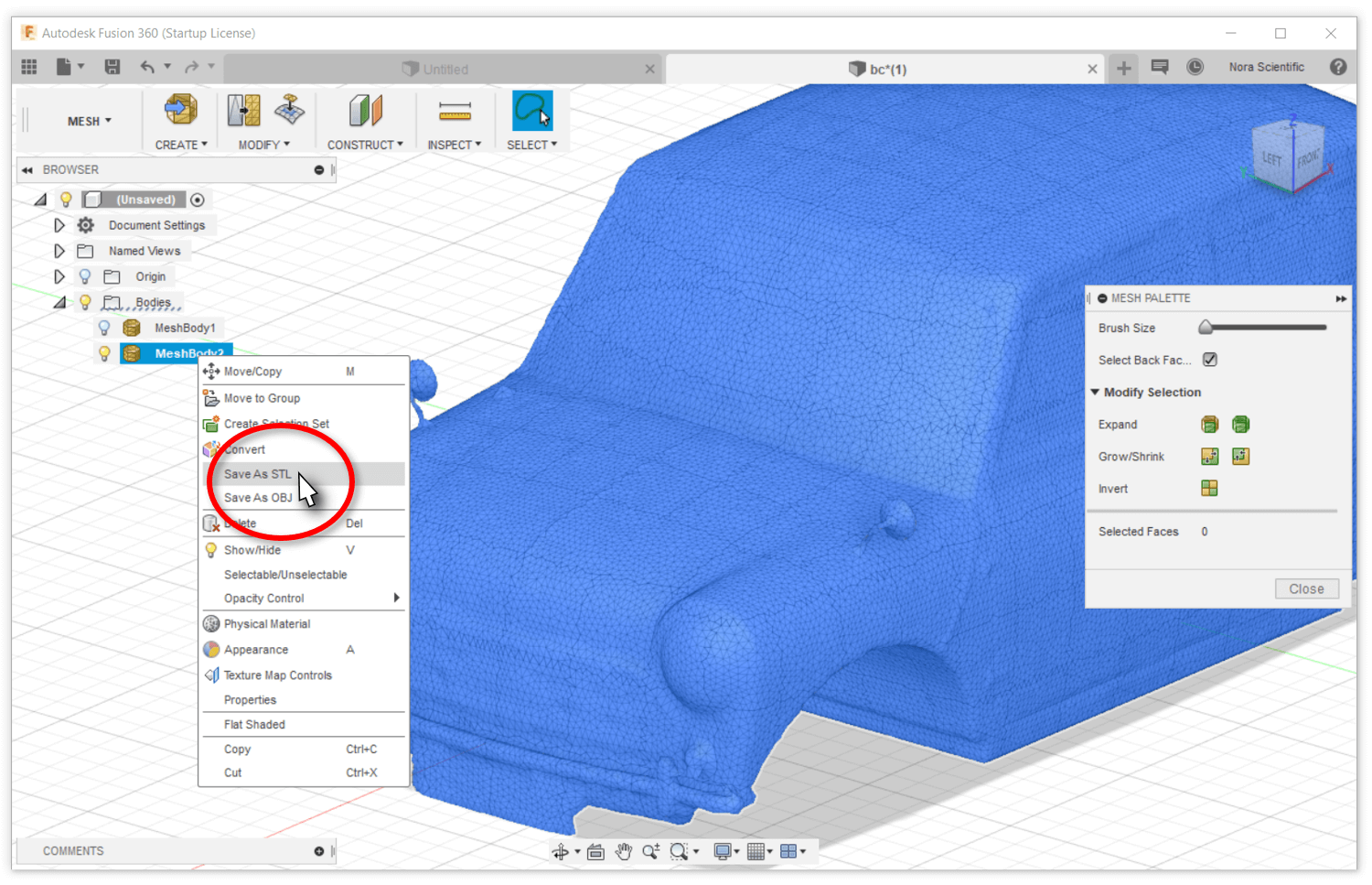
- Right moust click on "MeshBody2", which are generated in the above procedures. Click on "Save As STL" from the menu.
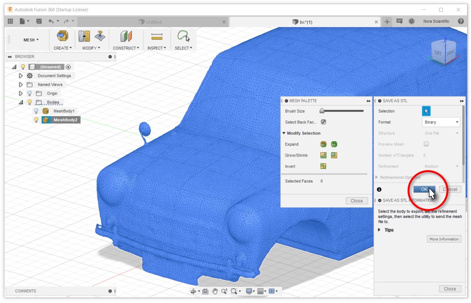
- Click on the "OK" button on the small "SAVE AS STL" window to save the model in a STL format. To import the model in Flowsquare+, please save the model in a STL format, in the same directory as the all other input files (param.txt, boundary configuration paint images) with the file name bc.stl.
12. Simulation Example with the Optimized Model
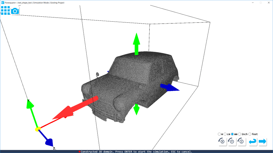
- Import the STL model (bc.stl), which are optimized and saved in the above procedures. Adjust the unit used in the STL file, model position and orientation in the Boundary Confirmation/STL Model Loader.
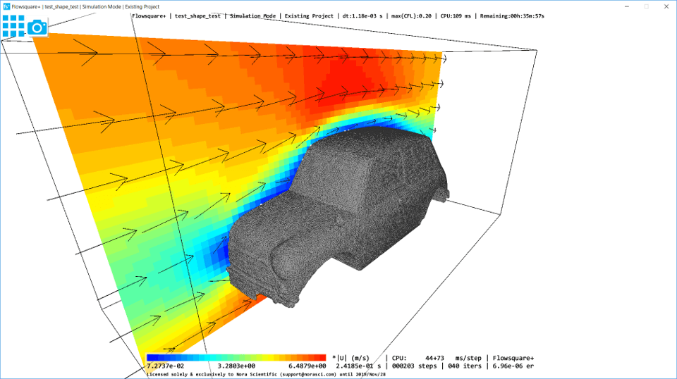
- After the adjustment, start the simulation.