The Easiest Computational Fluid Dynamics Software
 JP
JP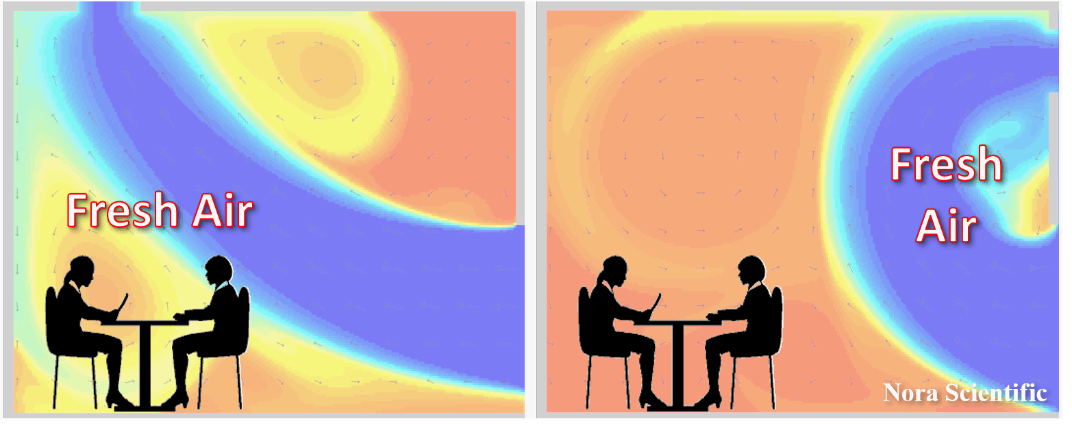
Fluid residence time (age variable, age of air)
This page introduces a new transported quantity, fluid residence time (age variable, age of air), which is implemented for the versions 2021R1.0 or later.
- What is age variable?
- Some rules about the age variable implementation
- Simulation example of age variable usage
- Mathematical aspect of the age variable
1. What is age variable?
The age variable is denoted by \(a\), and corresponds to the local residence time of the fluid at location \(x\) in the computational domain. Below images show typical age variable distributions in the simple flow fields (uniform flow and Karman vortex), where mean flow is from left to the right of the domain.
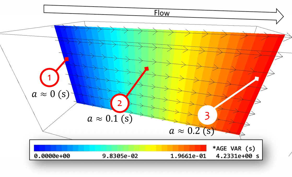
- The fluid near the inflow boundary spent short duration of time after entering the simulation domain, and yields a small age variable.
- The fluid located in middle of the domain spent substantial duration of time after entering the simulation domain, and yields a relatively large age variable.
- The fluid near the outflow boundary spent longest time after entering the domain, and yields the maximum value of age variable.
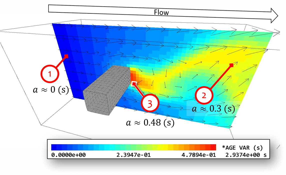
- The fluid near the inflow boundary spent short duration of time after entering the simulation domain, and yields a small age variable.
- The fluid near the outflow boundary spent relatively long time after entering the domain, and yields a relatively large value of age variable.
- The fluid located downstream of the object (bluff body) stay in the domain for very long time due to the small velocity. Therefore, they yield the maximum value for the age variable.
The age variable is useful to assess, for example, the room ventilation performance. Usually the performance of room ventilation is estimated based on the mean residence time of fluid defined by: \begin{equation} \tau = \frac{\text{volume of the room}}{\text{volumetric flow rate of the ventilation fan}}\:\: \rm{(s)}. \end{equation}
\(\tau\) is the time required to exchange the entire air in the room with the outside air.
Therefore, if a ventilation fan which can expel 1m\(^3\) air per every second in the room of 1m\(^3\), nominally, it is estimated to take 1 second before the entire air in the room is exchanged with the fresh air.
However, this estimation implicitly assumes that the air exchange happens homogeneously and uniformly. The level of uniformity of room ventilation largely depends on the layout of windows, doors and ventilation fans.
The below figure shows schematic examples of air flow with an optimal ventilation layout and nonoptimal layout. Using the same ventilation fan in the same volume room, it often ends up in very different fresh air flows.
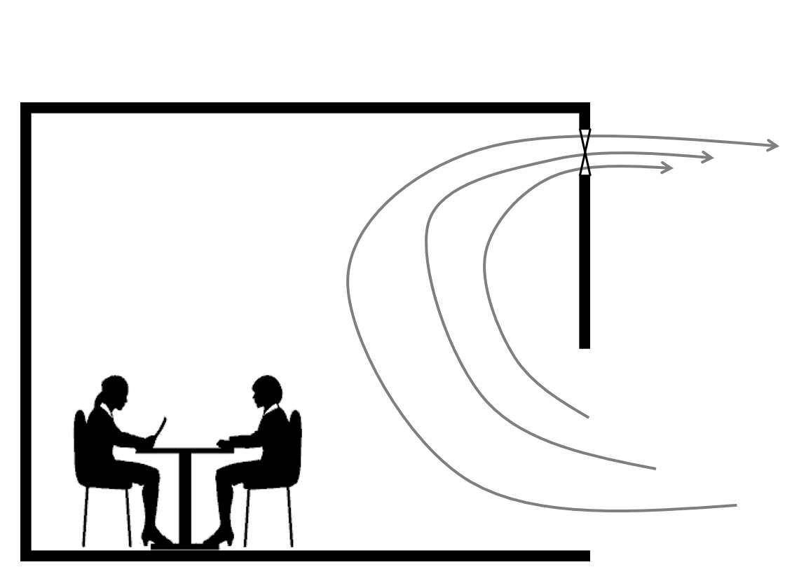
The age variable can show how long the fluid at location \(x\) stays in the domain of interest. Therefore, it can quantitatively tells which regions have rapid ventilation, and which region yields the same air for long time.
For room ventilation simulations, the regions with large age variable yields the same air for long time (non-fresh air), while the regions with small age variable yields the same air for a short duration of time (constant supply of fresh air) .
2. Some rules about the age variable implementation
- Rule #1
The unit of the age variable is second (s). - Rule #2
The age variable is taken to be \(a=0\) on the computational boundaries (\(i=1\), \(i=N_x\), \(j=1\), \(j=N_y\), \(k=1\), or \(k=N_z\)) if the boundary is specified by the preset color (blue, red, green, yellow or cyan) and with velocity going into the domain. - Rule #3
In the region specified by the preset colors (blue, red, green, yellow and cyan) where the parameters are set in a way that the velocity on the region is not constrained, the age variable is taken to be \(a=0\). For example, on the blue boundaries with uinB, vinB and winB being specified with " - " (hyphens), \(a=0\).
3. Simulation example of age variable usage
Input files (downloadable)
Let's perform example 2D simulations to understand the age variable. You can download input files used for the present simulations below.
- Optimal ventilation layout case
- Non-optimal ventilation layout case
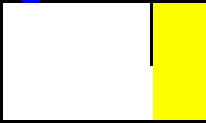
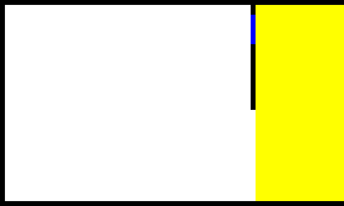
Boundary configuration image (bcXY0.bmp)
The following image shows the boundary configuration paint image (bcXY0.bmp) for the optimal ventilation layout case. Several important items labelled in the figure by numbers are described as follows.
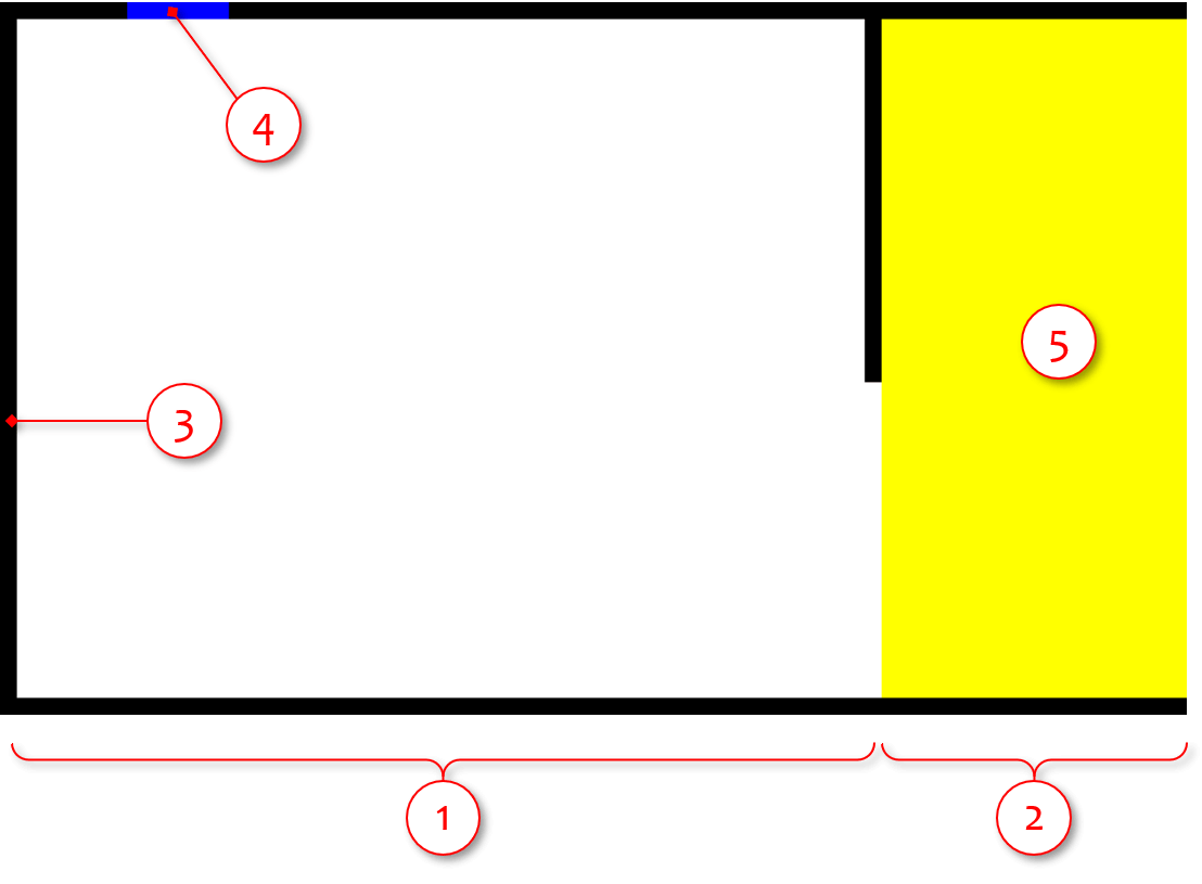
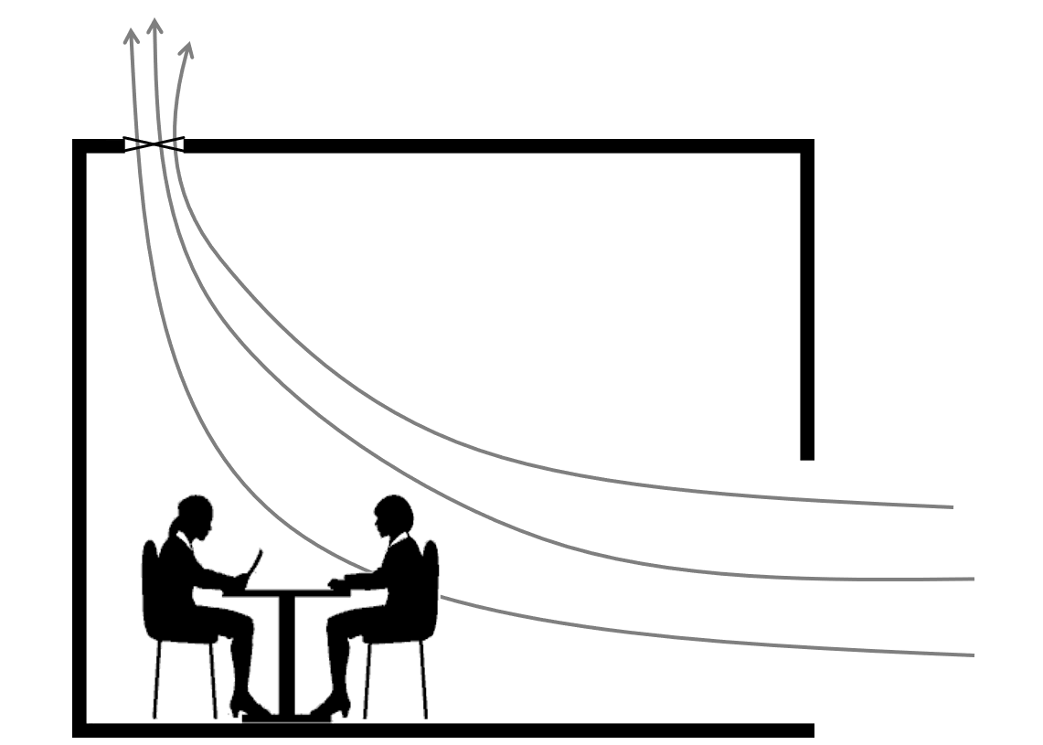
- Domain inside the room
This is the room and is the domain of interest. There is a ventilation fan on the top left of the room to expel the inside air to the outside. Also there is an opening section on the bottom right of the room. The negative pressure in the room due to the ventilation fan suck the outside (fresh) air from the opening section.
- Outside domain
Although the domain of interest is inside the room, the simulation needs to include the outside fluid, which is to be fed into the room. This is to avoid adverse effect of unknown information (of outside fluid) propagating into the simulation domain of interest.
- Wall boundary conditions (preset black color)
The room wall (and some outside region) are defined by the wall boundary conditions specified by the present black color.
- Ventilation fan (present blue color)
The ventilation fan, expelling the inside air to the outside, is specified as the constant velocity boundary by the present blue color. The specified fluid velocity on the boundary is point to the outside the room, as you can see in the parameter set later.
- Yellow boundary domain to reset the age variable
We want the age variable to start accumulating the residence time after entering the room. Thus, we need to set \(a=0\) in the outside region. To do that, yellow color is added in the entire outside region with the relevant velocity parameters, uinY = vinY (= winY for 3D) = " - " (hyphen). This does not influence the velocity, but constrain the age variable to be zero. See #3 in the Section 2.
Simulation parameters
Parameters for the optimal layout case are described below. More thorough information about parameters can be found here.
- cmode = 0
Simulation mode. For the present simulation, choose 0:Fluid simulation mode (constant density, constant temperature, single phase for gas and liquid flows).
- ageFlag = 1
Whether including the age variable transport equation during simulations (ageFlag=1) or not (ageFlag=0).
- parallel = 2
Level of parallelism. The option 2 corresponds to the low level parallelism, where #parallelism = max(1, maxThreadsAvail / 4).
- domx = 2000
Nominal horizontal window size during simulation (pixel).
- (nx, ny) = (300, 180)
Number of mesh points in \(x\) and \(y\) directions. The number of mesh points can be set independently from the physical domain size.
- (lx, ly) = (3.5, 2.1)
Simulation domain size in \(x\) and \(y\) directions (m).
- (sts, latts) = (0, 100000)
Time steps of the start and end of the simulation.
- (nfig, nfile) = (10000, 10000)
Frequency of saving simulation result image and dump data. The files are saved once in every timesteps specified here.
- presW = 1.0E+05
Mean pressure in the simulation domain (Pa).
- (uinB, vinB) = (0.0, 1.0)
A constant velocity component in \(x\) and \(y\)-direction (m/s) in the boundary region specified with the preset blue color in the boundary configuration images. In this optimal case, the inside air is expelled from the top ventilation fan towards outside at 1 m/s.
- (uinY, vinY) = ( - , - ) (hyphens)
A constant velocity component in \(x\) and \(y\)-direction (m/s) in the boundary region specified with the preset yellow color in the boundary configuration images. When the physical parameters including (uinY, vinY) are set with " - " (hyphen) instead of numbers, the boundary does not influence the corresponding physical quantities (the solution values from the transport equation are directly applied). Also, based on the #3 in section 2, if all velocity components (\(u\) and \(v\) for 2D and \(u\), \(v\) and \(w\) for 3D) are specified by " - " (hyphen), the age variable are taken to be \(a=0\) on the corresponding boundary.
- mu = 1.8E-5
Dynamic viscosity of fluid (Pa\(\cdot\)s) 。For standard condition mu = 1.8E-5 (Pa\(\cdot\)s) for the air.
- ndiv = 16
Interval mesh points of visualization objects such as velocity vectors, tracer particles, streamlines. These objects are (initially) generated at intervals of ndiv.
Simulation results
The images below show the simulation results of the optimal and non-optimal ventilation layout cases. The images show instantaneous age variable field, and there are four regions labelled as 1 to 4.
- The age variable outside region is always zero (\(a=0\)).
- The main stream, which consists of the fluid with very small age variable (fresh air). The residence time of the fluid after entering the room is \(a\ll100\) seconds.
- The secondary flows, which consist of the fluid with reasonably small age variable (reasonably fresh air). The residence time of the fluid after entering the room is \(a\approx150\) seconds.
- The region with small velocity, where the age variable is relatively large (the air is not so fresh). The residence time of the fluid after entering the room is more or less similar to the total simulation time.
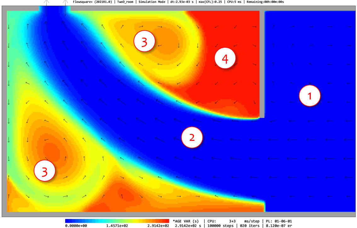
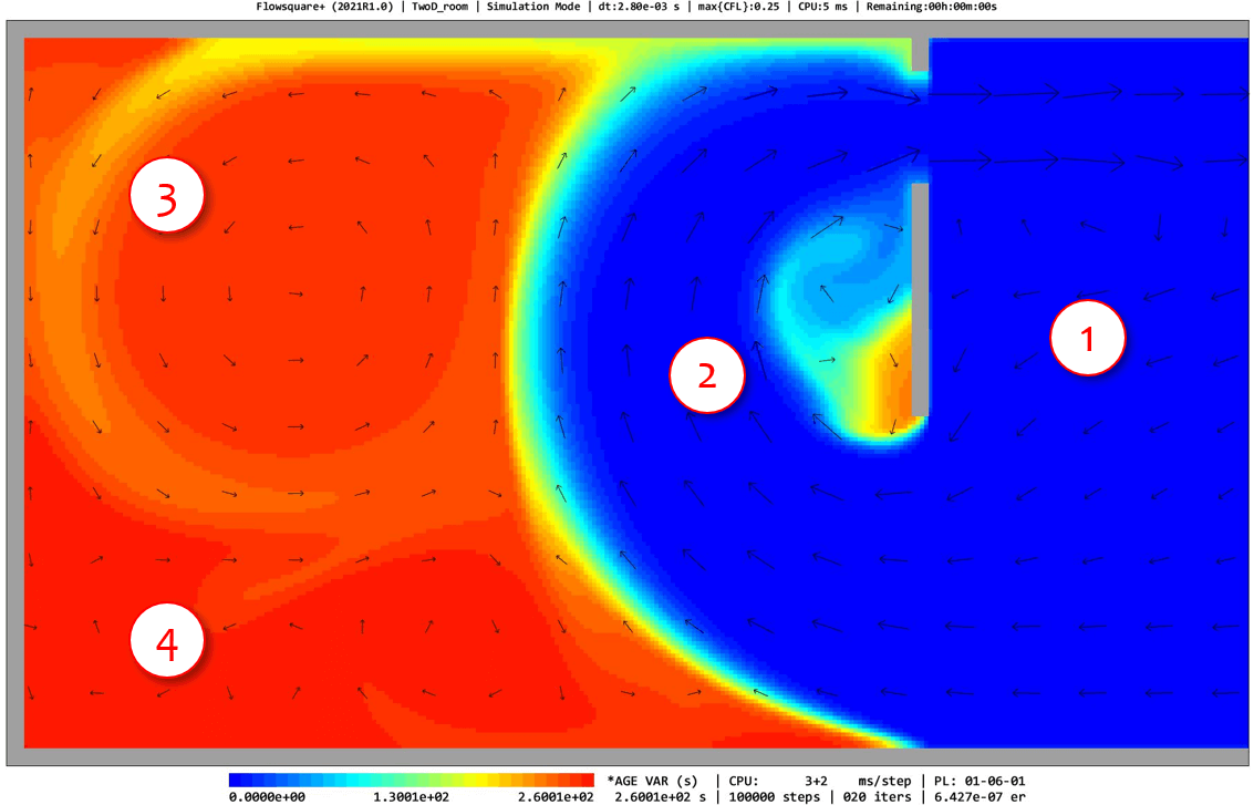
The two cases have identical ventilation fans with the same flow rate in the identical-sized room, while the layout of the ventilation fan is different. For the optimal case, the main stream and secondary flows bring fresh air in the large volume of the room, while for the non-optimal case, the relatively fresh air exists in a narrow region in the room and most inside air stays inside room for a longer period of time.
As demonstrated in this tutorial, the age variable can identify the local residence time (level of freshness) of the fluid quantitatively, which is not possible with the conventional estimation based on room volume and volumetric flow rate of the ventilation fan. The ventilation layout can be optimized based on the simulations with different parameter settings so that the small age variable is achieved at the region where fresh air is most needed.
4. Mathematical aspect of the age variable
In Section 1, the age variable was conceptually described. Here, mathematical aspect of the age variable is explained. The notation of various variables and used mathematical models are the same as description of solver page.
The transport equation of the age variable in the fluid \(a\): \begin{equation} \frac{\partial \bar{\rho} \tilde{a}}{\partial t} + \frac{\partial \bar{\rho} \tilde{u_i} \tilde{a}}{\partial x_i} = \frac{\partial}{\partial x_i} \left( \bar{\rho} D \frac{\partial \tilde{a}}{\partial x_i} \right) - \frac{\partial \bar{\rho} \phi_i^a}{\partial x_i} + \bar{\omega}_a, \end{equation}
The SGS scalar flux term for the age variable: \begin{equation} \phi_i^a = \widetilde{u_i a} - \tilde{u}_i \tilde{a}. \end{equation}
The source term of the age variable: \begin{equation} \bar{\omega}_a=1\:\:\rm{(kg/m^3/s)}. \end{equation}
Since the source term is \(\bar{\omega}_a=1\:\:\rm{(kg/m^3/s)}\), the local age variable accumulate 1 seconds per second as long as the fluid stays in the domain of interest. Therefore, as described in Section 1, the age variable corresponds to the local residence time of the fluid.
The boundary conditions imposed for the age variable is the same as other scalars (zero flux on the wall boundary). There are also additional constraints based on #1-#3 in the section 2.