The Easiest Computational Fluid Dynamics Software
 JP
JP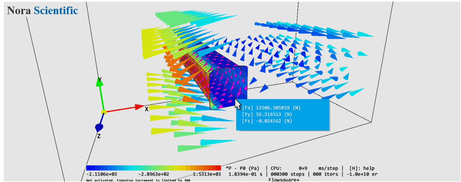
Basics of Flowsquare+
Simulation procedures in Flowsquare+ have following features. Step-by-step tutorial of performing a simulation with Flowsquare+ is explained in this page.
Boundary Configuration Images
The user can specify their own boundary condition, such as wall and inflow, by using few paint images.
These paint images consist of images for XY, YZ, ZX planes, and they are respectively named as XY#.bmp, YZ#.bmp, ZX#.bmp, where # is replaced by a number from 0 to 9. Therefore, maximum of ten images can be used for each direcion (eg. XY0.bmp, XY1.bmp, ..., XY9.bmp for XY direction). Only single XY plane (bcXY0.bmp) is necessary for 2D simulation.
A local boundary condition can be specified by a color in the bitmap image. By using seveal colors, the user can construct a relatively complex model with only several paint images.
More information about boundary configuration images and their preparation can be found here.
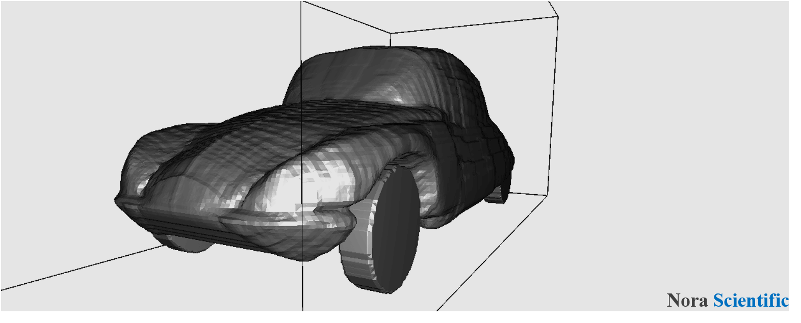
3D CAD Model
If the user need a little more complex model or already have design data, they can import a CAD model to construct their boundary condition.
In Flowsquare+, a CAD model with a STL format can be imported, and its file must be in the same directory with the other input files (paint images, param.txt). Also, the STL file must be bc.stl.
More information about CAD model and their preparation can be found here.
Parameters
Any parameter relevant to the simulation is specified in the Flowsquare+ interface and stored in param.txt.
These parameters can be edited freely by using Parameter Editor. The user can view a detailed description of each parameter in the editor, and the editor also performs some consistency check, so the user can know if their parameters are valid. The user can refer to various example simulation cases available for parameter setting.
More information about parameters can be found here.