The Easiest Computational Fluid Dynamics Software
 JP
JP
Vortices Suppression by Helical Strake Cylinder
1. Introduction
One of important engineering aspects of Karman vortex street is the periodic pressure fluctuation impinging on the cylinder. This pressure fluctuation synchronizes the occurrence of virtices from the cylinder, and produces stress on the sylinder. Also, this can cause noise.
Famous accidents directly or indirectly causes by these phenomena include Tacoma Narrows Bridge collapse and 1995 sodium leak and fire in Monju Nuclear Power Plant, and suppression of such oscillating flows phenomena is very importnat for various engineering products.
The present simulation example performs a simulation of the flow around a helical strake cylinder, which is often used to suppress generation of Karman vortex street in various fields.
All the input files required for this simulation can be downloaded from below. Should you choose to download the zip file, you need to unzip the file, and store the unzipped files in somehwere under FSP directory or subdirectory.
Input files
A typical computational time of this case is approximately 4 minutes per 1000 time steps with a typical Core i7 PC with the maximum parallelism setting (parallel in parameter setting).
2. Domain configuration
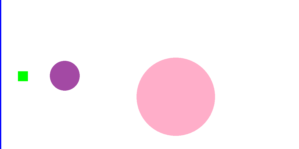
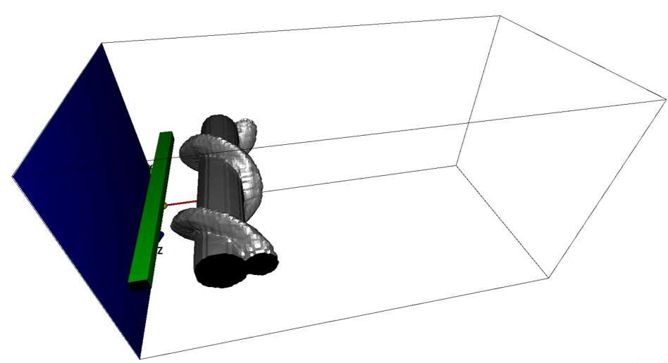
In the rectangular domain, there are an inflow boundary specificed by blue color, source of scalar (colored ink feed in the water) to visualize the flow field specified in green color in the downstream, and the solid wall (cylinder) to generate Karman vortex street specified by magenta color (non-preset color).
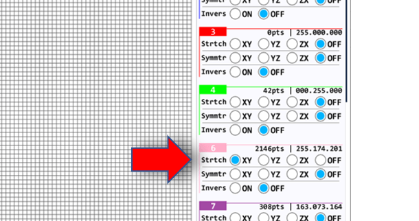
The helical structure stretching across Z-direction is specified by a pink color (non-preset color). Here, for the pink color, please do not forget to apply stretching in XY-plane (bcXY0.bmp).


3. Simulation parameters
The simulation parameters used in the present simulation are the same as "Karman vortex street". Only difference is that nz is increased to 100, to yields equal spatial resolution for X, Y and Z directions. This is because the present configuration is likely to produce various fluctuations in Z-direction due to the helical structure. General description of parameters in Flowsquare+ are explained in here.
4. Probe setting
To examine stress on the cylinder, probes are placed near upper and lower part of the cylinder. Also, you may add another probe downstream. Setting probes are explained in here.
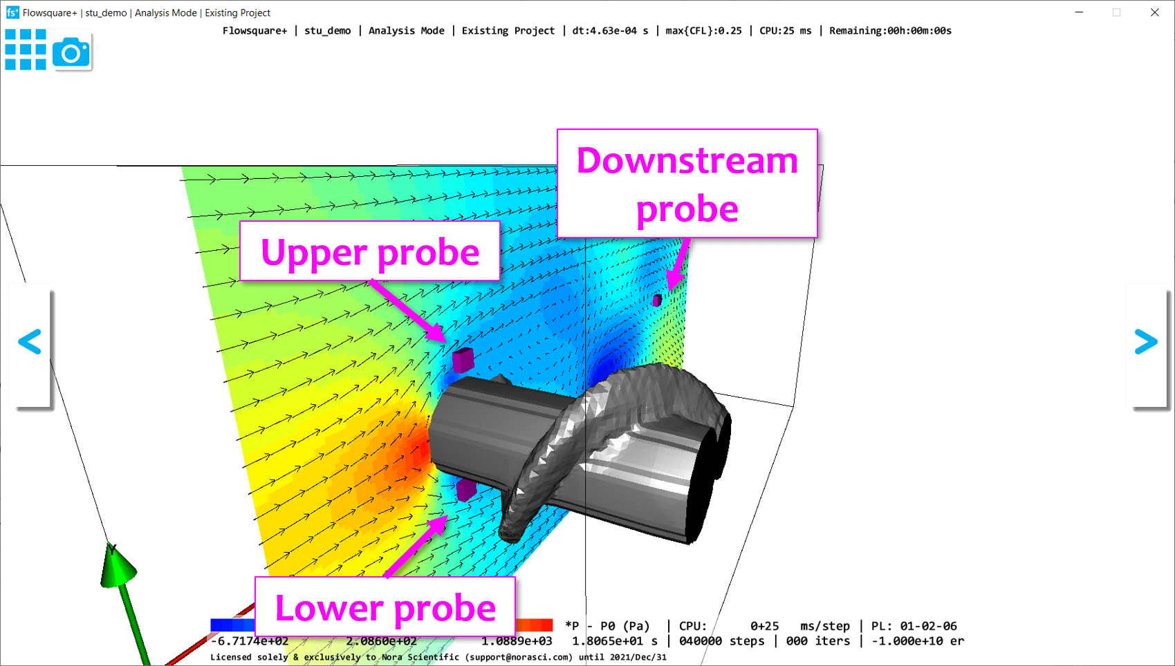
5. Simulation results
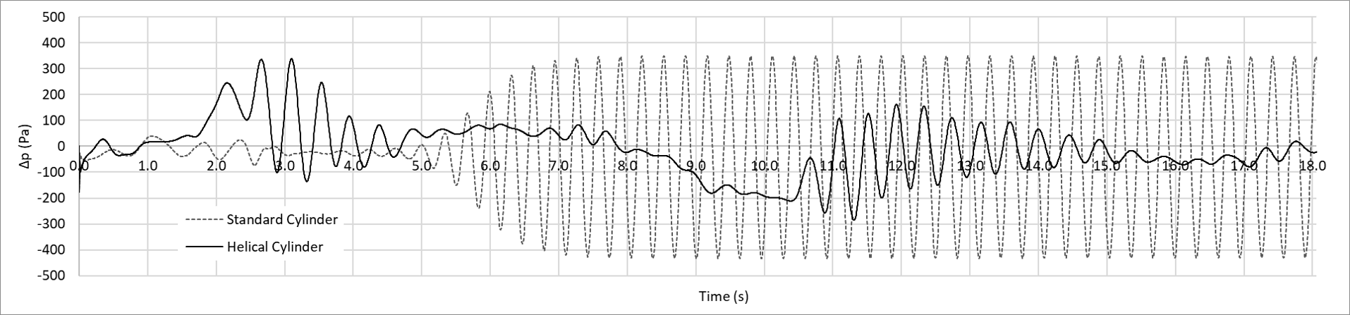
The simulation result is shown in movie below. The color shows the scalar mass fraction (colored ink feed in the water for visualization), and the evolution of the stress on the cylinder (the difference of the pressures measured by the upper and lower probes) is also shown. The result in the top row is for helical strake cylinder, and bottom row is for standard cylinder.
The evolution of the difference of the pressures measured by the upper and lower probes (\(\Delta p=p_{(upper)}-p_{(lower)}\)) is shown below. This pressure difference is directly related to the stress on the cylinder. With the helical cylinder, a quasi steady, periodic motion no longer exists, which suggests reduction of repetitive stress is greately suppressed.