The Easiest Computational Fluid Dynamics Software
 JP
JP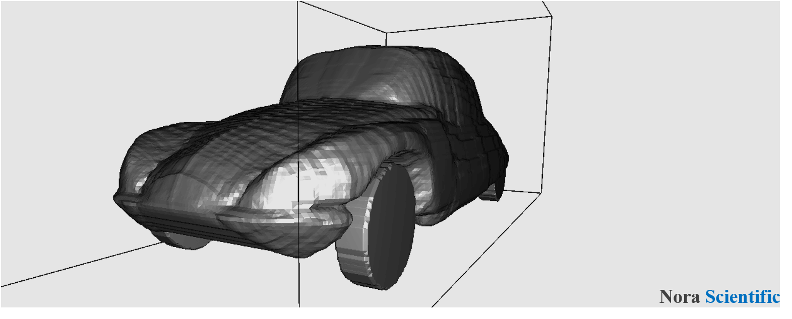
Paint Image Model Construction
This page describes the procedure using older versions of Flowsquare+ 2022R3.3. For operating procedures for the latest version (2023R1.0 or earlier), please click here.
1. Model configuration in Flowsquare+
There are three types of input files that Flowsquare+ uses: (1) parameter file, (2) paint images, and (3) CAD (STL) file. Here, the paint images and/or STL file are used only if necessary, and they are used to specify boundary conditions (BC; flow field model such as inflow and wall boundaries).
In this page, you will learn the methods and rules of 2D/3D model configuration based on single or multiple paint image(s).
2.Model configuration images
Boundary conditions (BC) such as wall and inflow boundaries can be specified by using bitmap images generated by any paint tool like Microsoft Paint.
These images consist of images for XY, YZ, ZX planes, and they are respectively named as bcXY#.bmp, bcYZ#.bmp, bcZX#.bmp, where # is replaced by a number from 0 to 9. Therefore, maximum of ten images can be used for each direcion (eg. bcXY0.bmp, bcXY1.bmp, ..., bcXY9.bmp for XY direction). Note that only single XY plane (bcXY0.bmp) is necessary for 2D simulation.
3. Color based boundary specification
A local boundary condition can be specified by a color code (RGB) in the bitmap image. A inflow boundary condition can be specified by
- BLUE (0, 0, 255)
- RED (255, 0, 0)
- GREEN (0, 255, 0)
- Yellow (255, 255, 0)
- Cyan (0, 255, 255)
- Magenta (255, 0, 255)
These specified inflow boundaries may be treated as (solid) wall boundary or outflow (suction) conditions, depending on the special arrangement specified in parameter setting for a corresponding color.
General wall boundary can be specified by
- BLACK (0, 0, 0).
Any region with
- WHITE (255, 255, 255)
is treated as fluid region, and if such a region is located on the computational boundary, the boundary is taken as an natural inflow/outflow (open) boundary.
These BLUE, RED, GREEN, YELLOW, CYAN, Magenta, BLACK, WHITE colors are named "preset colors". The other colors, "non-preset colors" or "user-specific colors", can be used to specify wall boundary, similar to the one specified by BLACK color. In the latest Flowsquare+, a total of 50 colors can be specified (Note that R2021R2.0 or earlier version allows 19 colors in total).
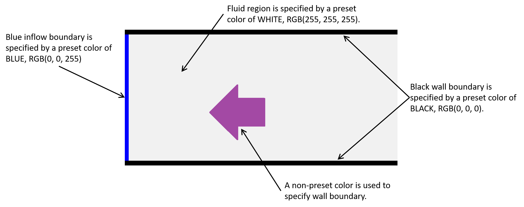
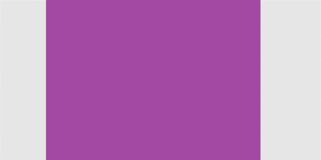
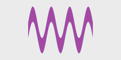
The below image shows an example image (bcXY0.bmp) to specify boundary conditions in a 2D flow field. Following the above rules, the image specify the simulation domain, where a fluid is fed from the left inflow boundary towards right, which is sandwiched between the uppper and lower walls. Also, there is an arrow-shaped object in the middle, which are specified by a user-specific color. A test simulation example using the below bcXY0.bmp is further explained in here.
4. Model configuration methods in Flowsquare+
Relatively complex 3D model can be constructed by combining few simple 3D models (elemental models). The below list summarizes methods to construct elemental models based on paint images.
- (a) Model with a uniform 2D cross-section
- (b) Model constructed by third angle projection
- (c) Bilaterally symmetric 3D model (Symmetric tool)
- (d) Model with a smoothly-changing 2D cross-section (Stretching tool)
- (e) Inverting a 3D object constructed based on above technique (Inverse tool)
- (f) 3D model consisting of few elemental objects constructed by using the above techniques
In Flowsquare+, the methods (a)-(f) can be applied for preset and non-preset colors to construct a complex fully-3D model. There are example simulation cases, which apply these techniques to achieve simulations for various problems.
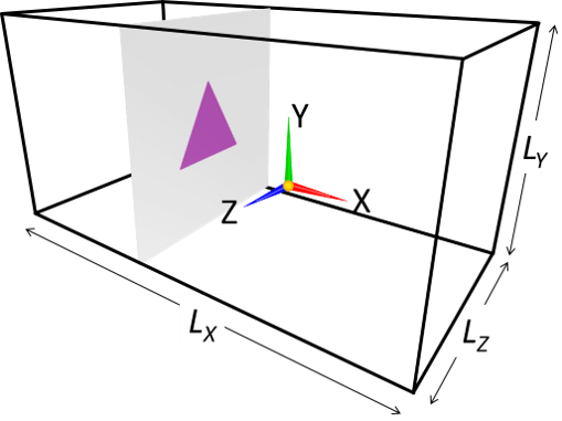
(a) Model with a uniform 2D cross-section
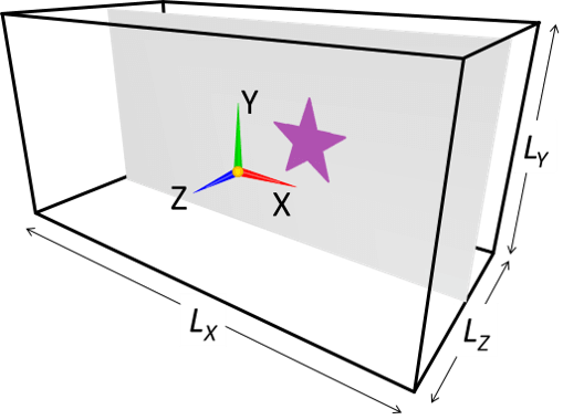
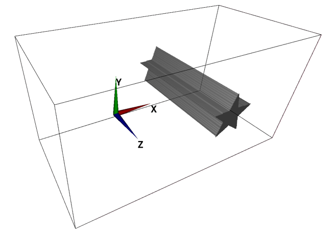
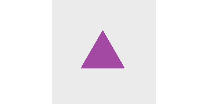
A simplest 3D object is an object with a uniform 2D cross-section. A cylinder and rectangular cylinder are some of such objects. Such objects can be specified with single image, which specifies the shape of cross-sectional cut of the 3D object (eg. if the cylinder spans in Z-direction, only XY cross-sectional shape of the object needs to be specified).

(b) Model constructed by third angle projection
A 3D object can be constructed by means of third angle projection. In such case, two or three cross-sectional images (eg. an image for XY-plane and another image for YZ-plane) needs to be prepared. These two images are basically projections of your object from their directions. You do not need to care too much about the pixel size or aspect ratio of images—images are automatically interpolated and adjusted to conform with the physical domain size specified by the parameters.
[(b) Supplemental]
In this method, an object is constructed by considering a volume of intersection of the "columns" with uniform 2D cross-sections specified in the two (orthogonal) paint images with a same color. If a subset of a column is not shared by the other image(s), the subset will not be a part of constructed 3D object. Here is such an example.

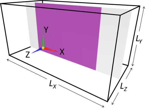

(c) Bilaterally symmetric 3D model (Symmetric tool)
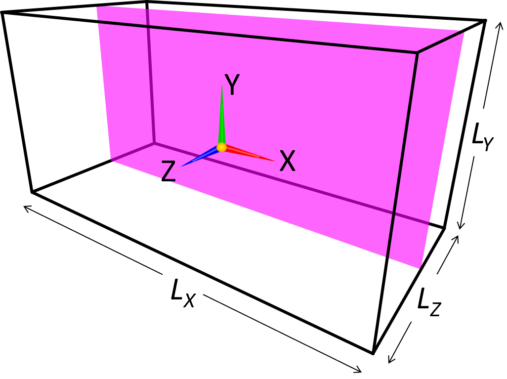
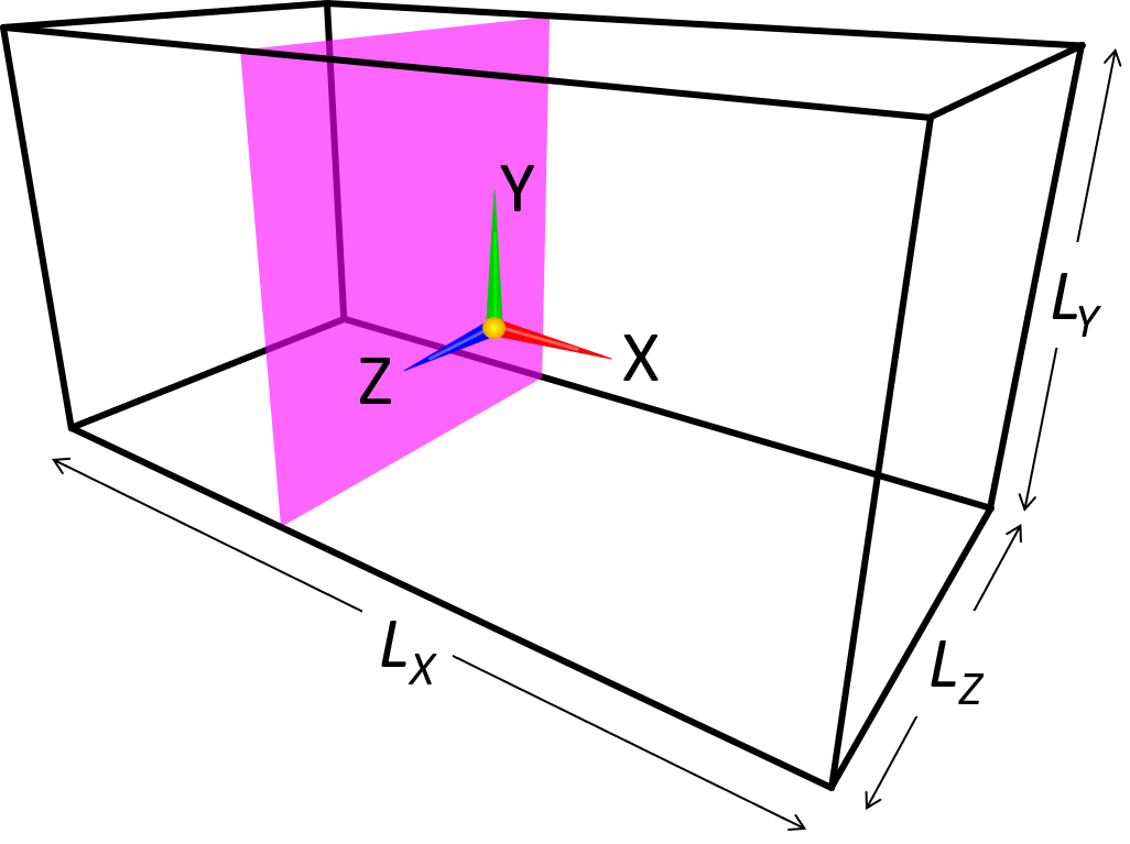
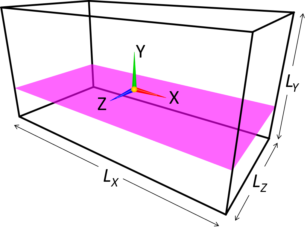
A symmetric model can be constructed by using "Symmetric" tool. In the Symmetric tool, you can select one of XY, YZ and ZX planes passing through domain center position as a symmetric plane.
The below exmaple construct an object symmetric about the XY plane passing through the domain center position.


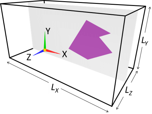
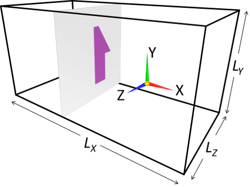
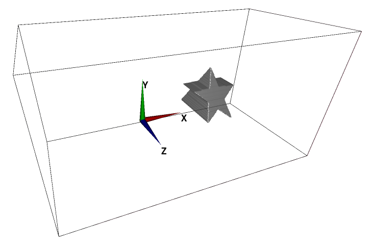
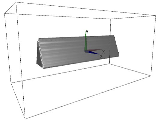
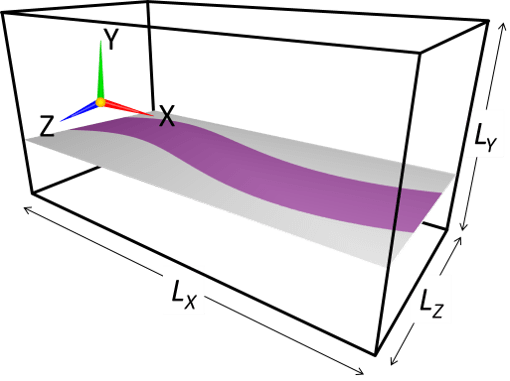
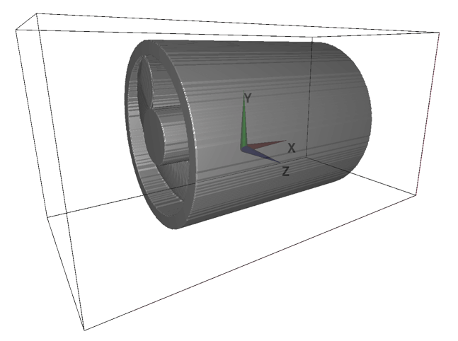
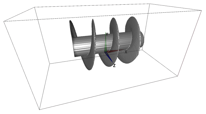
(d) Model with a smoothly-changing 2D cross-section (Stretching tool)
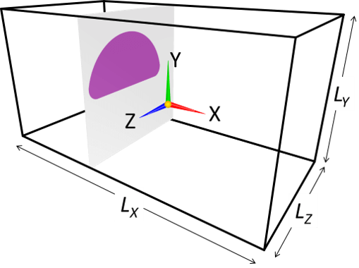
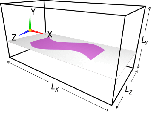
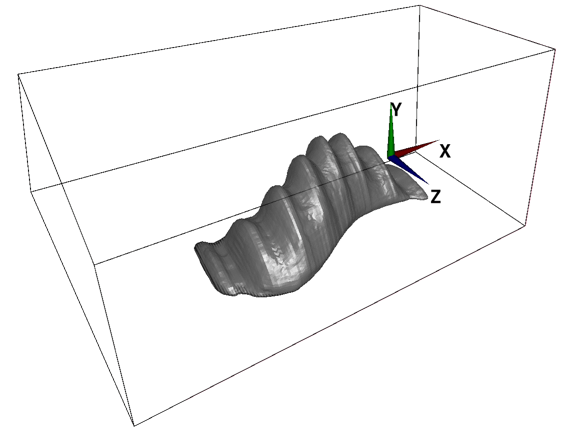
In Flowsquare+, a fully-3D model with a smoothly-changing 2D cross-section can also be constructed, by using "Stretching tool"*1. In the Stretching tool, you can select one of XY, YZ, and ZX planes, and Flowsquare+ "stretches" the 2D cross-sectional shape on that plane to fit shapes in the other one or two images with a same color, along its normal direction.
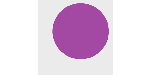
The following example shows a 3D model where YZ-cross-sectional shape is stretched to fit the shapes specified in XY and YZ images.


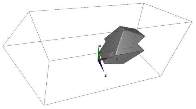
(e) Inverting a 3D object constructed based on above technique (Inverse tool)
The "Inverse tool" can be used to invert "inside" and "outside" of the 3D object constructed using the above techniques. Here, the inside could correspond to solid region and outside may correspond to fluid region. The following example shows how to construct "channel" like model.


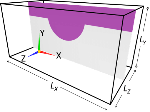
The below GIF animation shows a 3D models constructed based on the above images (e-1), (e-2) with and without the Inverse operation. The model shape does not change with and without the Inverse operation, but inside (solid) and outside (fluid) regions are switched due to the Inverse operation.
To identify a fluid and solid regions, you can use the 3D lighting option  on the tool pane— inside (solid) surface is always rendered with black color without considering lighting. Also, the ghost/solid display option
  shows white and grey points on the solid region near the wall on XY, YZ and ZX cross-sections.
(f) 3D model consisting of few elemental objects constructed by using the above techniques
Flowsquare+ can construct a 3D model by combining elemental objects constructed by using above configuration techniques. Each elemental object can be constructed by using a color different from the other elemental objects. This technique is called "Coloring technique"*1. The following example shows a 3D model consisting of two elemental objects which are constructed by using (b) third angle projection (images bcXY1.bmp、bcYZ1.bmp) and (d) the Stretching tool (images bcXY0.bmp、bcYZ0.bmp、bcZX0.bmp).


5. Applying configuration options for each color
The described methods (c), (d), and (e) can be selected in the boundary configuration image loader window on the right hand side of the window for each color including both preset and non-preset colors. If not used, select "OFF (default)". These selections are stored in input/bmp.txt and used in the future run.
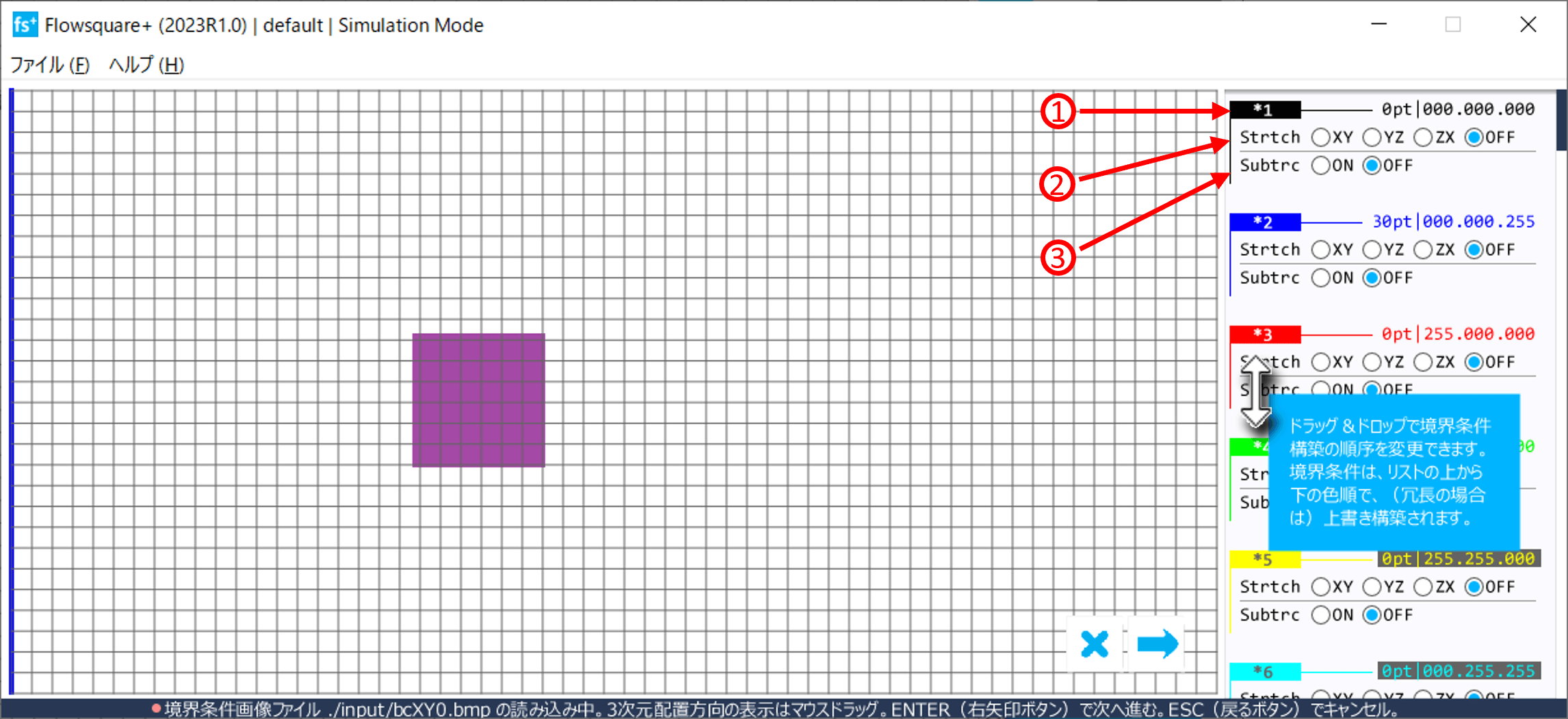
Descriptions of the numbered items in the above figure.
- Colour information
Information of each colour used in the model configuration images. Preset colours (black, blue, red and green) are always shown regardless of usage. - Strtch
Radio buttons to specify "Stretching" operation plane for each colour. A shape of the corresponding colour in the specified plane will be stretched. - Symmtr
Radio buttons to specify "Symmetric" operation plane for each colour. A constructed object of the corresponding colour will be symmetric about the specified plane. - Invers
Radio button to specify whether "Inverse" operation is performed for each colour.