The Easiest Computational Fluid Dynamics Software
 JP
JP
2D Flow Simulation
1. Numerical Configuration
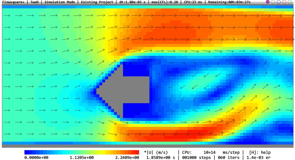
Here, we will perform a 2D flow simulation. 2D simulations usually require much less computational cost (time) yet including many important aspects of computational fluid dynamics (CFD). Therefore, a 2D flow simulation is a good case to get to know CFD for beginners.
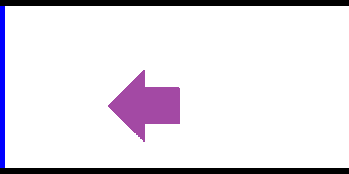
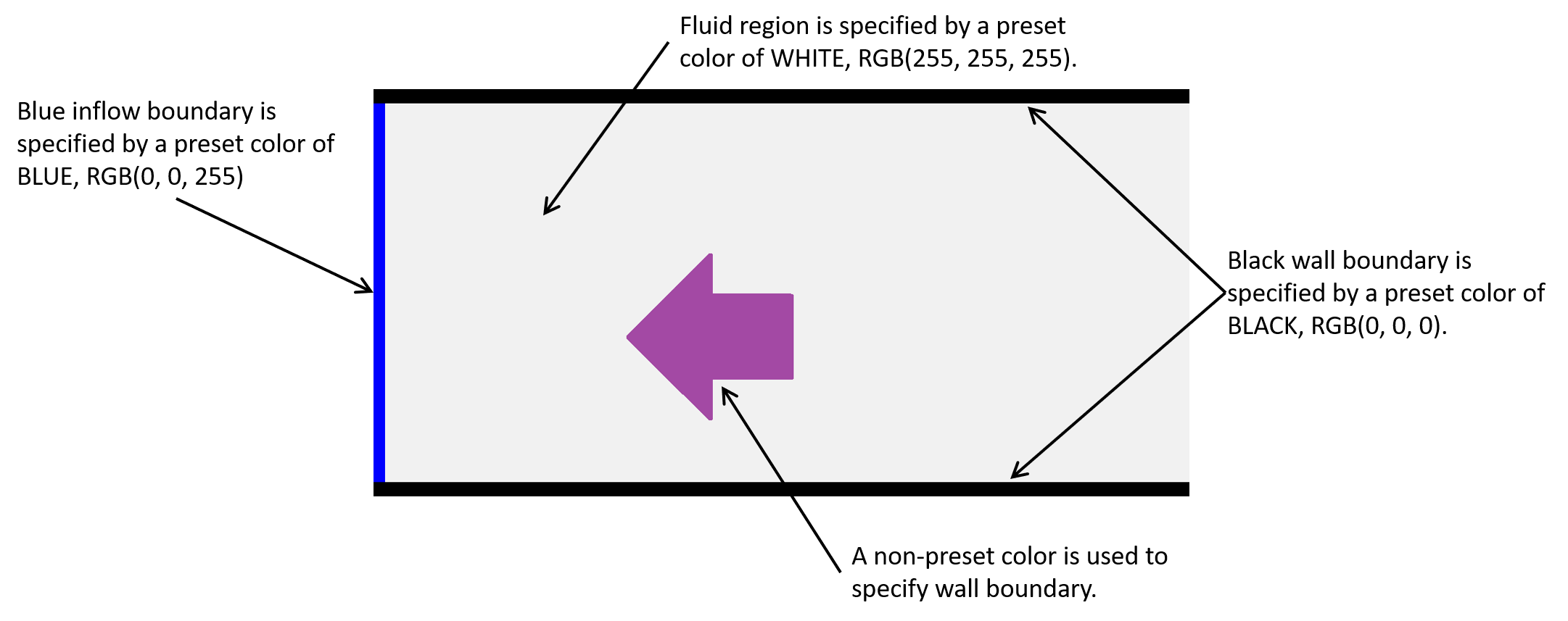
The computational domain set up is already explained in here with some details about how paint image works to specify the domain configuration.
All the input files required for this simulation can be downloaded below.
Input files
2. Numerical Parameters
All the required parameters are already set in the input files downloadable above. Several important parameters are explained here. More thorough information about parameters can be found here.
- cmode
cmode is taken as 0 for the fluid simulation mode (constant density, constant temperature, single phase for gas and liquid flows).
- lx
The domain length in X-direction is 2m.
- ly
The domain length in Y-direction is 1m.
- nx、ny、nz
The number of mesh points needs be determined based on the required spatial resolution. Here, we will use (nx, ny, nz) = (100, 50, 1), which yields the same mesh density for both directions. Also, in the parameter setting, nz is not specified as the default value of nz=1.
You may change the number of mesh points to see how different spatial resolution influences the solution.
- rhoW
Fluid density is taken as 1.2 kg/m^3, which corresponds to the air property at a standard condition.
- uinB
Inflow velocity at the blue inflow boundary is taken as 1m/s.
If you add nz and lz in the Parameter Editor and set numbers, you can perform 3D simulation on above configuration (e.g. lz=1m、nz=50).
3. Performing Simulation
Using the input files provided in the above link, you can perform the 2D flow simulation with following steps. These steps are described in more detail here.
- License activation (skippable; just press Enter)
- Setting project name
- Selecting preset domain configuration (skip; just press Enter)
- Setting input file path (only for a new project)
- Project confirmation
- Parameter setting (already set; just press Enter)
- Loading boundary configuration images (already set; just press Enter)
- Comfirming constructed boundary
- Starting your first simulation!