The Easiest Computational Fluid Dynamics Software
 JP
JP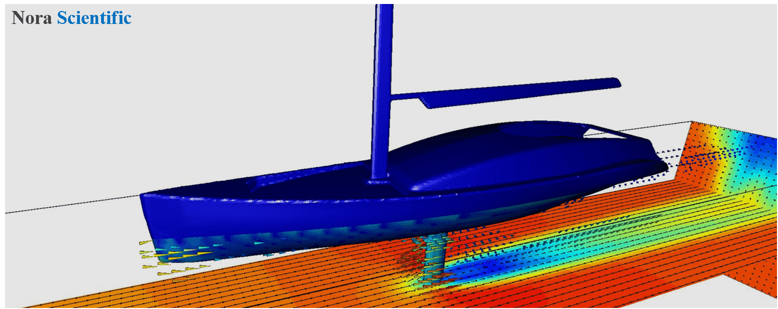
Flow through the Bottom and Keel of a Yacht
1. Introduction
We will learn how to use the slip boundary condition for the flow domain including an interface between liquid and gaseous fluid. Here, we assume that inertial force is more dominant in the liquid flow than the gaseous flow, and the gaseous flow does not influence the liquid flow and the height of the interface. Thus, we cannot predict ripple wave of the liquid surface, but still we can predict drag force imposed on by the liquid and flow around the boat!
The original CAD (STL) file we will be using here can be freely downloaded from GRABCAD. If the link does not work anymore, you can still download the original CAD (STL) file from here. In this tutorial, the original STL file is then modified and adjusted to correct mesh aspect ratio. For details, see "3D CAD (STL) Model and its Optimization". Generally, we do not want mesh having too large (or small) spect ratio. The optimised STL file is included in the following input file as well.
All the input files required to perform this simulation can be downloaded below. You need to unzip the file, and store the unzipped files in somehwere under FSP directory or subdirectory.
Input files
A typical computational time of this case is approximately 1 minute per 1000 time steps with a typical Core i7 PC with the maximum parallelism setting (parallel in parameter setting).
2. Simulation domain and boundary condition
Following simulation domain is construced with the present boundary configuration input files (bcXY0.bmp and bc.stl). Here, we specify an inflow boundary with the blue and slip boundary with the green preset colors (with appropriate parameter settings).

The slip boundary is the boundary, where only the boundary normal velocity component is always zero while boundary tangential velocity components are not influenced by the presence of the boundary. On the interface between the water and air, often the air flow does not influence too much the water flow. Also, when air flow is not too fast, we cound assume the vertical position of interface is constant (no wave).
In the present simulation, we use the green inflow boundary and use parameters to make it slip boundary to realise such water-air interface.

3. Simulation parameters
Several important parameters are explained here. More thorough information about parameters can be found here.
- cmode cmode is taken as 0 for the fluid simulation mode (constant density, constant temperature, single phase for gas and liquid flows).
- lx The domain length in X-direction is 7.0m.
- ly The domain length in Y-direction is 1.5m.
- lz The domain length in Z-direction is 1.5m.
- nx、ny、nz The number of mesh points needs be determined based on the required spatial resolution. Here, we will use (nx, ny, nz) = (200, 50, 50), which yields slightly finer mesh in Y and Z directions.
- rhoW Fluid density is taken as water value (997 kg/m^3).
- uinB, vinB, winB Inflow velocity for the blue inflow boundary is taken as (uinB, vinB, winB) = (10, 0, 0) m/s.
- uinG, vinG, winG The "inflow velocity" specified with the green preset color acts as slip boundary in this simulation. For that purpose, the velocity is taken as (uinG, vinG, winG) = (-, 0, -) m/s. More information about the slip boudanry parameter setting can be found here.
- rhoW Fluid viscosity is taken as water value (1.0E-3 kg/m/s).
4. Simulation results
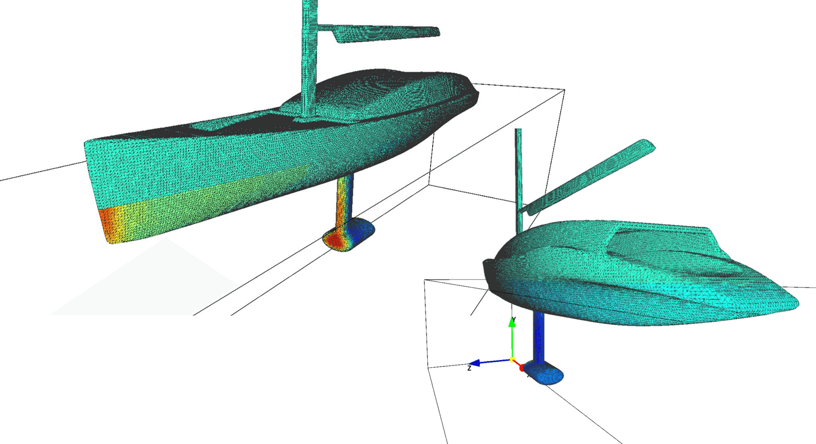
You can visualize the flow field using various tools in Flowsquare+, during and after the simulations using "analysis mode". The visualized field can be manually saved in a jpg format by using the camera button  .
.
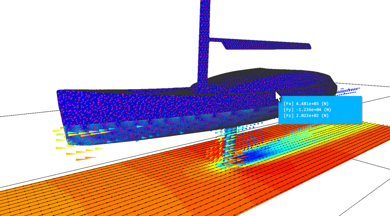
The instantaneous XZ velocity, uncorrelated vectors, and external forces imposed by the water flow on the yacht. To compute the fluid force, use  from the tool pane.